11.4 Use of slope distances in adjustment calculations
Having made these corrections to s, it might now seem reasonable to calculate dR manually, using equation 11.24 followed by equation 11.6, and feed this result into the network adjustment calculations. For really accurate work, however, this is still precluded by unknown effects on the observed vertical angle caused by the exact atmospheric conditions at the time of the observation; these effects mean that equation 11.24 may give an erroneous result, particularly along a steeply sloping ray.3 It is therefore best to feed slope distances into a precise network adjustment, rather than horizontal or reduced distances. Note, however, that the heights of the two stations will then also be required by the adjustment program; the absolute heights need only be correct to about 10 m, but the difference in heights should be correct to within 0.1 m, or even less on a short or steeply sloping ray.
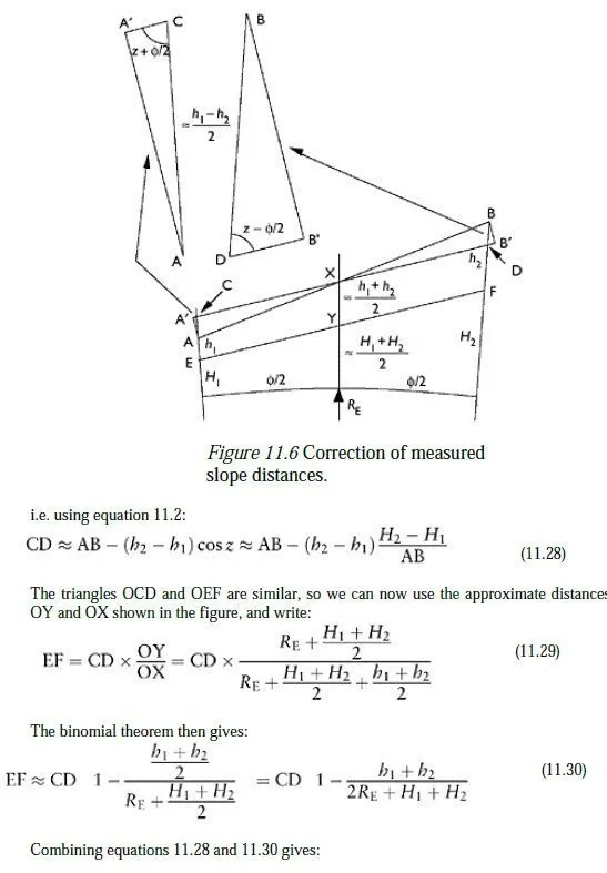
The use of slope distances may involve one further operation on the distance computed in equation 11.26. Since this is a distance from instrument to target, it may need to be adjusted manually to give a slope distance between the two actual stations before it can be fed into a network adjustment program. An approximate formula for this correction can be derived from Figure 11.6, in which A and B represent the instrument and target, and E and F the stations over which they are positioned.
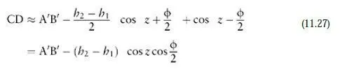
,e start by rotating the line AB about X, the point where it crosses the angular bisector of OA and OB (where O is the centre of the earth), until it is parallel with the line between the two stations. This gives the line A²B², which is then shortened to give the line CD. Because Φ is very small, the lengths AC and BD are both approximately (h2−h1)/2, so we can write:
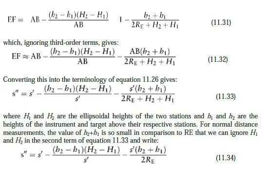
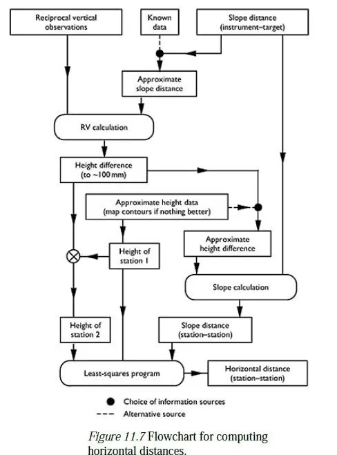
This means that we do not need to know the absolute values of H2 and H1 to find s³, but merely the difference between them, which typically only needs to be known4 to within about 0.1 m to preserve an accuracy of 1 part per million in equation 11.34. The values of h1 and h2 need to be known to within about 2 mm, which can be achieved by measuring the heights of instrument and target with a tape. A suitable value for H2−H1 would nowadays typically be found using GPS; where this is not practicable it can be found by levelling or by using reciprocal vertical angles as described in Chapter 12. A worksheet for adjusting measured slope distances using the formulae developed in Sections 11.3 and 11.4 is given in Appendix H. A flowchart showing how the necessary information can be collected for an adjustment involving distances is shown in Figure 11.7. The observation of reciprocal vertical angles and the resulting calculations, which are referred to in the Figure, are discussed in the next chapter.
11.5 Summary
The essential points covered by this chapter are as follows:
1 EDMs are capable of calculating horizontal distances, but only at the altitude of the observing station. To obtain a reduced horizontal distance on the ellipsoid, equation 11.6 must be applied.
2 All observed vertical angles are affected by atmospheric effects. It is possible to make some allowance for this by using an effective earth radius in place of the real one, but this makes assumptions about the atmosphere which may not be true in practice. Under these circumstances, the calculation of a horizontal distance from a slope distance and vertical angle will be in error, particularly when the slope is steep.
3 The remedy is to use the slope distance in the adjustment combined with the heights of the two stations, which must therefore both be known. Although the atmospheric effects mentioned above affect the measurement of slope distance as well, the effect is very small in practice.
4 A measured slope distance (instrument to target) may need to be adjusted to a stationto-station distance before it can be used by an adjustment program.