The height differences between control points are often explicitly required in engineering surveying work. Even when they are not, they must (for instance) be found before distance measurements can be used in accurate surveying work, as shown in Chapter 11. The methods for measuring height differences covered earlier in this book are levelling (for short distances, or for maximum accuracy up to 25 km) and GPS for longer distances, or for shorter distances not requiring accuracies better than about 2 cm. GPS gives the relative heights of stations to a more than adequate accuracy for the processing of distance measurements, but suffers from the following drawbacks:
1 It is not possible to use GPS with confidence (or perhaps even at all) near buildings, in excavations and tunnels, or beneath tree canopies.
2 Height information from GPS is less accurate than horizontal positioning information. It is possible to get accuracies of the order of 1 cm in height differences, but at least 24 h of observation are required.
3 The conversion of GPS height differences to differences in orthometric height requires an accurate and reliable geoidal model and even the best models may not be as accurate as they are believed to be, where there is significant local distortion of the geoid. If the model uses a co-ordinate system other than the one on which the GPS observations are based, a reliable transformation is also required.
4 There is no truly independent check to ensure that results from GPS observations are correct. Redundancy can be achieved by making additional GPS observations, but all the results are subsequently processed using the same software. An error in this software, or in the transformation parameters, or in the geoidal model, will remain undetected.
Conventional methods do not suffer from these drawbacks, but conventional levelling over large distances or height differences is extremely time-consuming. In addition, some height differences are simply unsuitable for measurement by conventional means; the height of a tall building or a cliff face, for instance. This chapter therefore presents an alternative approach to finding height differences which, if used carefully, is capable of results which are accurate to within 5 mm over distances of the order of 2 km, and over height differences of the order of 200 m without the need to occupy any stations in between. In Chapter 11, it was shown how the slope distance between two stations can be used to compute the horizontal distance and height difference, if the vertical angle of the target from the instrument is known. Unfortunately, any vertical angle which is observed by the instrument is affected by atmospheric conditions along the light path, as shown in Figure 11.5. These conditions cannot easily be measured, making it impossible to estimate accurately the amount by which an observation might have been affected.
If the vertical angle is measured from both stations simultaneously, however, most of these atmospheric effects can be eliminated simply by taking the average of the two readings. The use of reciprocal vertical angles (RVs), as such measurements are called, can therefore enable the height difference between two stations to be calculated to a high degree of accuracy, with an observation time which is short by comparison with other available methods.
12.1 Procedure
To take RV measurements between two stations, theodolites are set up over each station, and targets are set up on auxiliary stations, a short distance from each instrument. The bearing from each instrument to its nearby target is perpendicular to the bearing between the two instruments. Both these bearings are also in the same direction, so that the two lines of sight between each instrument and its distant target cross each other, as shown in plan in Figure 12.1. Each auxiliary station is set up by observing the distant main station approximately from the local main station (an accuracy of 1² is sufficient), then swinging the theodolite through 90° and setting the auxiliary station
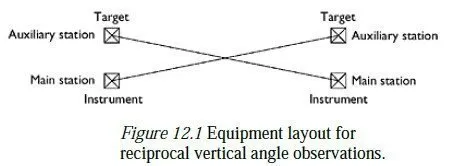
between two and four metres away1 on the given line of sight. If the layout of the land near the two main stations means that the auxiliary stations have to be on opposite bearings from their main stations, one of the targets is now put on the main station, with the instrument on the auxiliary station, so that the lines of sight between each instrument and its distant target still cross. The heights of both the instrument and the target above their nearby main station are now found, at each end of the operation. This can be done by using the vertical circle to set the theodolite telescope horizontal, and then using the instrument as a level.
A scheme for recording the information needed to find the necessary heights is shown as part of the booking sheet for RV observations, in Appendix G. Typically, the height of the instrument above the main station is first measured, using a tape measure. The tape is then held vertically against the target in some way, and two readings are taken; one at the level of the targets centre and one on the line of collimation from the instrument. The difference between the two readings gives the difference in height between the target and the instrument. It is also important to note whether the instrument is higher or lower than the target, as this will not be obvious when the readings are processed back at base. On the form shown in the appendix, this is done by filling in the target higher or target lower box, as appropriate. Two boxes are provided for each reading, so that height measurements can be taken both before and after the main observations. Simultaneous vertical angle observations are now taken by each theodolite to the distant target, with the circle-left and circle-right readings being taken as quickly as possible after each other to minimise the effects of atmospheric changes along the light path. Making these observations quickly, and simultaneously at each station, greatly improves the accuracy of the result. This can best be achieved by having an observer and a booker at each station, with the bookers in radio contact. As the agreed time for an observation approaches, each observer should ensure that the sighting and vernier settings are approximately correct, and that the alidade bubble is set exactly. At the exact start time for the observation, each observer makes a final adjustment to the vertical tangent screw and takes the first reading. The instrument is then quickly transitted to the other face, and the telescope is immediately aimed exactly at the target; once that has been done, there is no further need for haste. The alidade bubble can now be set again, and the second angle reading recorded. Two or more further observations are then taken separated by about 5 min (of time), to allow for the possibility of unusual atmospheric conditions on one occasion. Each circle-right reading is subtracted from 360°, and the result is compared with the corresponding circle-left reading. The differences may be found to be anything up to about 30 seconds;3 but it is important that, for each theodolite, all the differences are the same to within about 5 seconds. If any difference does not meet this criterion, then that set of readings (and the corresponding set from the other station) must be discarded, and a further set of readings taken after another 5 min wait. This can happen either because of observation error, or because of a change in atmospheric conditions between the circleleft and circle-right readings e.g. if one was done in sunlight and the other when the sun was behind a cloud. A booking sheet for recording RV observations is given in Appendix G. It is important that both observing teams should note the same times for each observation on their booking sheets, so that the corresponding pairs of readings can be identified when the results are discussed and computed. When three or more mutually acceptable sets of readings have been taken, the heights of the instrument and target at each station should be re-measured, using the same procedure as before. A slope distance would normally then be measured as well, using an EDM above one main station and a reflector above the other. This measurement is needed to adjust the instrument-to-target vertical angles collected above to station-tostation values; but it will probably also be used to find the slope distance between the two stations, as described in Sections 11.3 and 11.4.