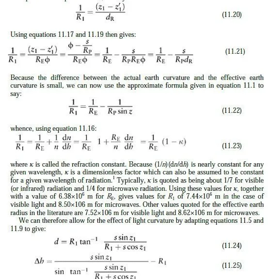
where R1 is the effective radius of earth curvature for visible light and z1 the actual zenith angle observed by the instrument. The appropriate value for R1 can be built into an EDM device, enabling it to calculate reasonably accurate horizontal and vertical distances for any sighting within its operating range.
For precise work, however, it is unsatisfactory to simply use the horizontal distance reported by an EDM device, even allowing for the fact that it has not been reduced to the geoid. There are three main reasons for this. First, it is not always possible to find out exactly how a given instrument computes its horizontal distances. Second and most importantly, local atmospheric conditions may mean that the value of R1 used by the device when applying equations 11.24 and 11.25 is quite inappropriate.2 Third, it is usually better practice to measure an unconnected distance in the field, and compute precise corrections to it subsequently, in the office. These corrections will be discussed next.
11.3 Corrections to distance measurements
The correction of raw measured distances involves three steps. First, the mean velocity (and therefore wavelength) of electromagnetic radiation along the straight line between instrument and target is not a known, constant value, but depends on the temperature and pressure of the air along the line. For some types of radiation, the humidity of the air must also be taken into account. The correction for this is made using a formula or table supplied by the instrument manufacturer, as it is a function of the wavelength and modulation of the radiation used by the instrument. The atmospheric conditions used for this correction are usually the mean values of those measured at each end of the ray; this is reasonably accurate for pressure, but note that it may be substantially inaccurate for temperature if, say, the instrument and target are on opposite sides of a deep valley. Second, allowance must be made for the fact that the air above the straight line path is slightly less dense than the air on the straight line path, so the radiation will in fact propagate more quickly through it; this is, after all, what causes the light path between the stations to curve as described in Section 11.2. It is therefore necessary to calculate the path through the atmosphere which the radiation will propagate along in the minimum time, and allow for the fact that the mean wavelength along this new path will be longer than the value calculated above. Finally, having now effectively calculated the distance along this new curved path, an arc to chord calculation is carried out to find the distance along the original straight path. These last two adjustments are both very small, and indeed tend to cancel each other out. It is therefore common to roll them together into a single correction formula, which makes use of our earlier assumption about the way in which the refractive index (and therefore the propagation velocity) varies with altitude in the earths atmosphere. The formula quoted by Bomford (1980) is:
where s is the distance corrected for mean atmospheric conditions and κ the refraction constant defined in equation 11.23