The following four methods are available for carrying out plane table survey:
1. Radiation
2. Intersection
3. Traversing
4. Resection.
The first two methods are employed for locating details while the other two methods are used for locating position of plane table station on drawing sheet.
14.3.1 Radiation
After setting the plane table on a station, say O, it is required to find the plotted position of various objects A, B, C, D ….. . To get these positions, the rays OA, OB, OC ….. are drawn with soft pencil (Ref. Fig. 14.7). Then the distances OA, OB, OC ….., are measured scaled down and the positions of A, B, C ….., are found on the drawing sheets.
This method is suitable for surveying small areas and is convenient if the distances to be measured are small. For larger areas this method has wider scope, if telescopic alidade is used, in which the distances are measured technometrically.

Intersection
In this method the plotted position of an object is obtained by plotting rays to the object from two stations. The intersection gives the plotted position. Thus it needs the linear measurements only between the station points and do not need the measurements to the objects. Figure 14.8 shows the method for locating objects A and B from plane table positions O1 and O2.

This method is commonly employed for locating:
(a) details
(b) the distant and inaccessible points
(c) the stations which may be used latter.
14.3.3 Traversing
This is the method used for locating plane table survey stations. In this method, ray is drawn to next station before shifting the table and distance between the stations measured. The distance is scaled down and next station is located. After setting the plane table at new station orientation is achieved by back sighting. To ensure additional checks, rays are taken to other stations also, whenever it is possible. Figure 14.9 shows a scheme of plane table survey of closed area. This method can be used for open traverses also.

Resection
This method is just opposite to the method of intersection. In the method of intersection, the plotted position of stations are known and the plotted position of objects are obtained by intersection. In this method the plotted position of objects are known and the plotted position of station is obtained. If a, b and c are the plotted positions of objects A, B and C respectively, to locate instrument station P on the paper, the orientation of table is achieved with the help of a, b, c and then resectors Aa, Bb, Cc are drawn to get the p , the plotted position of P. Hence in the resection method major work is to ensure suitable orientation by any one of the methods. The following methods are employed in the method of resection:
(a) by compass
(b) by back sighting
(c) by solving two point problem
(d) by solving three point problem.
(a) Resection after Orientation by Compass: Let a and b be the plotted positions of A and B of two well defined points in the field. Keeping the through compass along north direction marked on the drawing sheet table is oriented on station P, the position of which is to be found on paper. The resectors Aa and Bb [Fig. 14.10] are drawn to locate p the plotted position of station point P. This method gives satisfactory results, if the area is not influenced by local attractions. It is used for small scale mapping only.

(b) Resection after Orientation by Back Sighting: Figure 14.11 shows the scheme of resection after orientation by back sighting. From station A, the position of B is plotted as b and ray has been taken to station P as ap². Then plane table is set at P and oriented by back sighting A, line AP is not measured but the position of P is obtained on the paper by taking resection Bb.

(c) Resection after Solving Two Point Problem: The problem of finding plotted position of the station point occupied by the plane table with the help of plotted positions of two well defined points is known as solving two point problem. Figure 14.12 shows the scheme of solving this.

Let A and B be two well defined points like lightening conductor or spire of church, the plotted positions a and b already known. Now the problem is to orient the table at P so that by resection its plotted position p can be obtained. The following steps may be followed to solve this problems:
(i) Select a suitable point Q near P such that the angles PAQ and PBQ are not accute.
(ii) Roughly orient the table at Q and draw the resectors Aa and Bb to get the point q.
(iii) Draw the ray qp and locate p1 with estimated distance QP.
(iv) Shift the plane table to P and orient the table by back sighting to Q.
(v) Draw the resector Aa to get p.
(vi) Draw the ray pB. Let it intersect line bq at b1.
(vii) The points b and b1 are not coinciding due to the angular error in the orientation of table. The angle bab, is the angular error in orientation. To correct it,
* Fix a ranging rod at R along ab, * Unclamp the table and rotate it till line ab sights ranging rod at R. Then clamp the table. This gives the correct orientation of the table which was used in plotting the points A and B. (viii) The resectors Aa and Bb are drawn to get the correct plotted position p of the station P.
(d) Resection after Solving Three Point Problem: Locating the plotted position of a station point using observations to three well defined points whose plotted positions are known, is called solving three point problem.
Let A, B, C be three well defined objects on the field whose plotted positions a, b and c are known. Now the problem is to locate plotted position of the station point P. Any one of the following methods can be used.
(i) Mechanical (Tracing paper) method,
(ii) Graphical method, or
(iii) Trial and error method (Lehmans method).
(i) Mechanical Method: This method is known as tracing paper method since it needs a tracing paper. The method involved the following steps [Ref. Fig. 14.13.]

* Set the table over station P and by observation approximately orient the table.
* Fix the tracing paper on the plane table and select P approximately, say as p². From p², draw p² A, p² B and p² C. These lines may not pass through the plotted positions a, b and c since the orientation is not exact.
* Loosen the tracing paper and rotate it so that the rays pass through respective points a, b and c. Now prick the point p² to get the plotted position p of the station P.
* Keep the alidade along pa and sight A. Then clamp the table. This is correct orientation.
Check the orientation by observing along pb and pc.
(ii) Graphical Method: The following two graphical methods are available to solve three point problem:
* Bessels solution
* Method of perpendiculars.
Bessels Solution: It involves the following steps:
1. Keep the bevelled edge of alidade along ba and sight object at A. Clamp the table and draw
bc² along the line bc [Fig. 14.14 (a)].
2. Keep bevelled edge of alidade along ab, unclamp the table and sight B. Clamp the table.
Draw line ac intersecting bc² at d [Fig. 14.14(b)].
3. Keep the alidade along dc and bisect C. Clamp the table [Fig. 14.14(c)]. This gives the
correct orientation.
4. Draw resectors to get p.

Method of Perpendiculars
This is another graphical method. It involves the following steps [Ref. Fig. 14.15].
1. Draw line ae perpendicular to ab. Keep alidade along ea and turn the table till A is sighted. Clamp the table and draw the ray Bb to intersect the ray Aac at e [Fig. 14.15(a)].
2. Draw cf perpendicular to bc and clamp the table when fcC are in a line. Draw Bb to intersect
Ccf at F [Fig. 14.15(b)].

3. Join cf drop bp perpendicular to ef to get the plotted position p.
4. Orient the table such that pbB are in a line. Clamp the table to place it in correct orientation.
Resections Aa and Cc may be used to check the orientation.
Trial and Error Method
This method is also known as triangle of error method and Lehmans Method. It involves the following steps:
1. Set the table over point P and orient the table approximately, just by observation.
2. Draw the rays aA, bB and cC [Fig. 14.16]. If the orientation was perfect, the three rays would have intersected at a single point, i.e. at point p. Otherwise a triangle of error is formed.
3. To eliminate the triangle of error an approximate position, ray p², is selected near the triangle
of error. Then keeping alidade along p²a object A is sighted and the table is clamped. Draw the resectors cC and bB to check the orientation.
4. Above step is repeated till triangle of error is eliminated.

Lehman presented the following guidelines to select p² so that triangle of error is eliminated quickly.
Rule 1: The distance of point sought p is in the same proportion from the corresponding rays as the distance of those from the plane table station.
Rule 2: The point sought p is on the same side of all the three resectors.
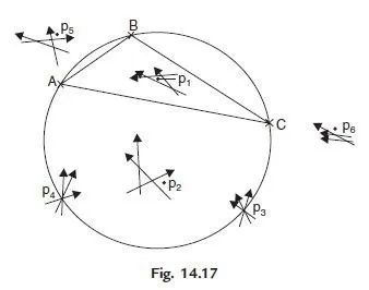
Defining the triangle ABC on the field as great triangle and the circle passing through them as great circle, from the above two rules of Lehman, the following sub-rules may be drawn [Ref. Fig. 14.17].
* If P lies within the great triangle, the point p is within the triangle of error (p1 in the Fig. 14.17).
* If the plane table station P lies outside the great triangle the point sought p is outside the triangle of errors (p2).
* If the P is on the great circle, the correct solution is impossible (p3 and p4).
* If P is outside the great circle, p is nearer to the intersection of rays to the nearest two points (P5).
* If point P is outside the great circle and the two rays drawn are parallel to each other the point sought is outside the parallel lines and on the same side of the three rays (P6).


really intresting and precise notes and observations…
very good, our professor lecture was made of pics only and guess waht i just found those pics were copied from here haha,,
I inspired from Table Surveying i am surprise to see the accuracy in this method.