The purpose of this section is to provide a preview of the principal methods of analysis used in this volume, and to show that most of them are straightforward applications of methods in common use for steel or for concrete structures.
The steel designer will be familiar with the elementary elastic theory of bending, and the simple plastic theory in which the whole cross-section of a member is assumed to be at yield, in either tension or compression. Both theories are used for composite members, the differences being as follows:
concrete in tension is usually neglected in elastic theory, and always neglected in plastic theory;
in the elastic theory, concrete in compression is transformed to steel by dividing its breadth by the modular ratio Ea/Ec.
in the plastic theory, the equivalent yield stress of concrete in compression is assumed in Eurocodes 2 and 4 to be 0.85 fck, where fck is the characteristic cylinder strength of the concrete. Examples of this method will be found in Sections 3.5.3 and 5.6.4.
In the UK, the compressive strength of concrete is specified as a cube strength, fcu. In the strength classes defined in the Eurocodes (C20/25 to C50/60) the ratios fck/fcu rangefrom 0.78 to 0.83, so the stress 0.85 fck corresponds to a value between 0.66 fcu and 0.70 fcu. It is thus consistent with BS 5950 (14) which uses 0.67 fcu for the unfactored plastic resistance of cross sections.
The factor 0.85 takes account of several differences between a standard cylinder test and what concrete experiences in a structural member. These include the longer duration of loading in the structure, the presence of a stress gradient across the section considered, and differences in the boundary conditions for the concrete.
The concrete designer will be familiar with the method of transformed section, and with the rectangular-stress-block theory outlined above. Fig 1.2 The basic difference from the elastic behaviour of reinforced concrete beams is that the steel section in a composite beam is more than tension reinforcement, because it has a significant bending stiffness of its own. It also resists most of the vertical shear.

The formulae for the elastic properties of composite sections are more complex that those for steel or reinforced concrete sections. The chief reason is that the neutral axis for bending may lie in the web, the steel flange, or the concrete flange of the member. The theory is not in principle any more complex than the used for a steel I-beam.
Longitudinal shear
Students usually find this subject troublesome even though the formula

Repeated use of (1.19) for various cross-sections shows that the variation of longitudinal shear stress is parabolic in the web and linear in the flanges, as shown in Fig.1.2.
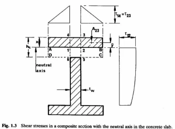
The second example is the elastic beam shown in section in Fig.1.3. This represents a composite beam in sagging bending, with the neutral axis at depth x, a concrete slab of thickness hc, and the interface between the slab and the structural steel (which is assumed to have no top flange) at level 6-5. the concrete has been transformed to steel, so the cross-hatched area is the equivalent steel section. The concrete in area ABCD is assumed to be cracked, to resist no longitudinal stress, but to be capable of transferring shear stress.
Equation (1.19) is based on rate of change of bending stress, so in applying it here, area ABCD is omitted when the excluded area is calculated. Let the cross-hatched area of flange be Af, as before. The longitudinal shear stress on plane 6-5 is given by
For plane 6-5, the shear force per unit length of beam (symbol v), equal to Ï„ 65 tw, is more meaningful than 65 Ï„ because this is the force resisted by the shear connectors, according to elastic theory. This theory is used for the design of shear connection in bridge decks, but not in buildings, as there is a simpler ultimate-strength method (Section 3.6).
For a plane such as 2-3, the longitudinal shear force per unit length is given by equation (1.19)
as

It is not equal to Ï„23 because the cracked concrete can resist shear; and it does not have to be divided by the modular ratio, even though the transformed section is of steel, because the transformation is of widths, not depths. This is a stress on an area that has not been reduced by transformation. An alternative explanation is that shear forces v from equation (1.21) are independent of the material considered, because transformation does not alter the ration A23/I.
The variation of Ï„23 across the width of the concrete flange is triangular as shown at the top of Fig.1.3.
Longitudinal slip
Shear connectors are not rigid, so that a small longitudinal slip occurs between the steel and concrete components of a composite beam. The problem does not arise in other types of structure, and relevant analyses are quite complex (Section 2.6 and Appendix A). They are not needed in design, for which simplified method have been developed.
Deflections
The effects of creep and shrinkage make the calculation of deflections in reinforced concrete beams more complex than for steel beams, but the limiting span/depth ratios given in codes such as BS 8110(18) provide a simple means of checking for excessive deflection. These are unreliable for composite beams, especially where unpropped construction is used, so deflections are normally checked by calculations similar to those used for reinforced concrete, as shown in Section 3.7.
Vertical shear
The methods used for steel beams are applicable also to composite beams. In beams with slender webs, some advantage can be taken of the connection of the steel beam to a concrete slab; but the resistance of a concrete flange to vertical shear is normally neglected, as it is much less than that of the steel member.
Buckling of flanges and webs of beams
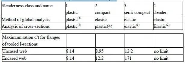
This will be a new problem to many designers of reinforced concrete. In continuous beams it leads to restrictions on the slenderness of unstiffened flanges and webs (Section 3.5.2). In Eurocode 4, these are identical to those given for steel beams in Eurocode 3; and in the British code,(14) the values for webs are slightly more restrictive than those for steel beams.
Crack-width control
The maximum spacings for reinforcing bars recommended in codes for reinforced concrete are intended to limit the widths of cracks in concrete, for reasons of appearance and to avoid corrosion of reinforcement. On composite structures for buildings, cracking is likely to be a problem only in encased beams, or where the top surfaces of continuous beams are exposed to corrosion. The principles of crack-width control are as for reinforced concrete, but calculations may be more complicated (Section 4.2.5). They can nomally be avoided by using the bar-spacing rules given in Eurocode 4.
Continuous beams
In developing a simple design method for continuous beams in buildings (Chapter 4), use has been made of the simple plastic theory (as used for steel structures) and of redistribution of moments (as used for concrete structures.)
Columns
The only British code that gives the design method for composite columns is BS 5400 : Part 5 , composite bridges and that method (described in Chapter 14, Volume 2) is rather complex for use in buildings. Eurocode 4 given a new and simpler method, developed in Germany, which is described in Section 5.6.
Framed structures for buildings
Framed satisfiers for buildings Composite members normally form part of a frame that is essentially steel, rather than concrete, so the design methods given in Eurocode 4(Section 5.4) are based on those of Eurocode 3, for steel structures. Beam-to-column connections are classified in the same way, and the same criteria are used for classifying frames as braced of untraced and as sway or non-sway. No design method for composite frames has yet been developed that is both simple and rational, and much research is in progress, particularly on design using semi-rigid connections.
Structural fire design
The high thermal conductivity of structural steel and profiled steel sheeting causes them to lose strength in fire more quickly than concrete does. Structures for buildings are required to have fire resistance of minimum duration (typically, 30 minutes to 2 hours) to enable occupants to escape, and to protect fire fighters. This leads to the provision either of minimum thicknesses of concrete and areas of reinforcement, or of thermal insulation for steelwork. Fire testing combined with parametric studies by finite-element analysis have led to reliable design methods. Fire engineering is an extensive subject, so only a few of these methods are explained here, in Sections 3.3.7, 3.1., and 5.6.2, with worked examples in Sections 3.4.6. and 3.11.4.


