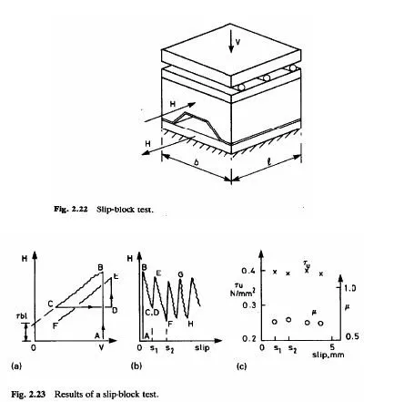
This test has been developed in Australia since 1989(30.31) for profiles that provide ductile shear connection A piece of sheeting one wavelength wide provide ductile shear connection A piece of sheeing one wavelength wide and about 300 mm long is attached by spot welding to a badssscplate (Fig2.22) A cover slab of similar thickness to the composite slab is cast on it vertical load V is applied through rollers, and a horizontal force H as shown in the figure Longitudinal slip ,Sis measured.
The procedure is illustrated in Fig 2.23 Bond is broken in a preliminary test A load v is applied (point A) and kept constant while H is increased until slip begins (point A),and kept constant while H is increased until slip begins (Point B). The load v is then slowly reduced so that slipping occurs and H falls off slightly this is continued until the block is about to lift at one end (point C.).

Load V is again increased (to point D).and the cycle is repeated ,this time at slightly greater slip .Further cycles follow ,as shown by slip lincs GH etc ,on Fig 2.23 (b) The slope of each slip line gives a value for the coefficient of friction u ,and its intercept on the H-axis in Fig 2.23 (a )gives a value for bl where Tu is the mean shear stress per unit horizontal area , because.
of composite slabs are obtained when the values used correspond to between 2 mm and 3 mm of slip in the slip-block test.
The design procedure for a composite slab using this method is explained in Section 3.4.3.


