Minimum Flexural Reinforcement by 2008 MSJC Code
The 2008 MSJC Code has no global requirements for minimum flexural reinforcement for shear walls.
Maximum Flexural Reinforcement by 2008 MSJC Code
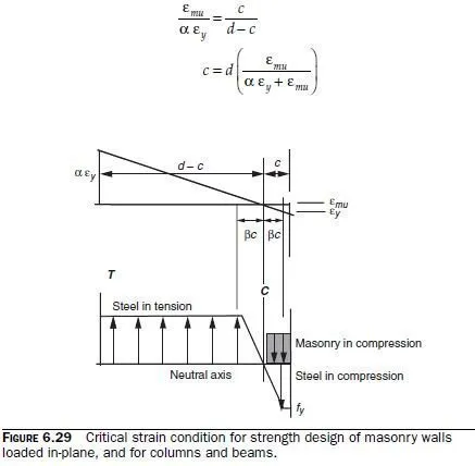
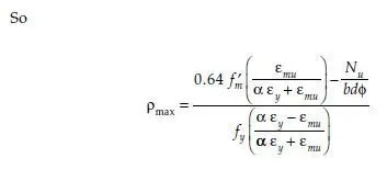
The 2008 MSJC Code has a maximum reinforcement requirement (Sec. 3.3.3.5) that is intended to ensure ductile behavior over a range of axial loads. As compressive axial load increases, the maximum permissible reinforcement percentage decreases. For compressive axial loads above a critical value, the maximum permissible reinforcement percentage drops to zero, and design is impossible unless the cross-sectional area of the element is increased. For walls subjected to in-plane forces, for columns, and for beams, the provisions of the 2008 MSJC Code set the maximum permissible reinforcement based on a critical strain condition in which the masonry is at its maximum useful strain, and the extreme tension reinforcement is set at a multiple of the yield strain, where the multiple depends on the expected curvature ductility demand on the wall. For special reinforced masonry shear walls, the multiple is 4; for intermediate walls, it is 3. For walls not required to undergo inelastic deformations, no upper limit is imposed.
The critical strain condition for walls loaded in-plane, and for columns and beams, is shown in Fig. 6.29, along with the corresponding stress state. The multiple is termed α. The parameters for the equivalent rectangular stress block are the same as those used for conventional flexural design. The height of the stress block is 0.80 fm², and the depth is 0.80c. The stress in yielded tensile reinforcement is assumed to be fy. Compression reinforcement is included in the calculation, based on the assumption that protecting the compression toe will permit the masonry there to provide lateral support to the compression reinforcement. This assumption, while perhaps reasonable, is not consistent with that used for calculation of moment-axial force interaction diagrams.
Locate the neutral axis using the critical strain condition:

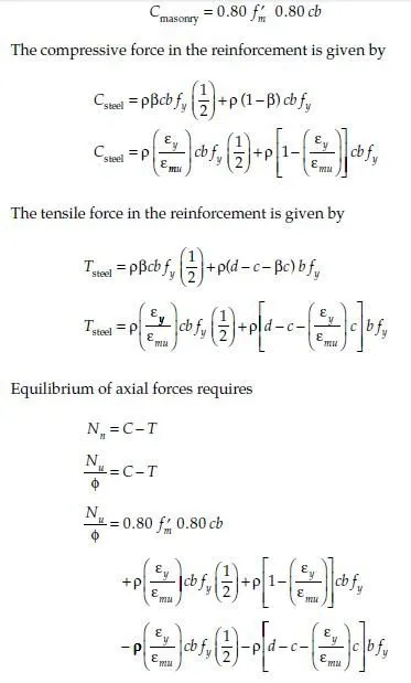
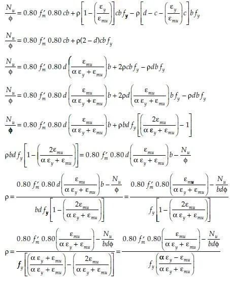
Compute the tensile and compressive forces acting on the section, assuming uniformly distributed flexural reinforcement, with a percentage of reinforcement Ï =A bd s/ .On each side of the neutral axis, the distance over which the reinforcement, in the elastic range, is βc, where β is given by proportion as β = ε ε y mu / .
The compressive force in the masonry is given by


