Based on our discussion in Section 3.4, we can define a plane truss as internally stable if the number and geometric arrangement of its members is such that the truss does not change its shape and remains a rigid body when detached from the supports. The term internal is used here to refer to the number and arrangement of members contained within the truss. The instability due to insufficient external supports or due to improper arrangement of external supports is referred to as external.
Basic Truss Element
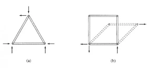
The simplest internally stable (or rigid) plane truss can be formed by connecting three members at their ends by hinges to form a triangle, as shown in Fig. 4.9(a). This triangular truss is called the basic truss element. Note that this triangular truss is internally stable in the sense that it is a rigid body that will not change its shape under loads. In contrast, a rectangular truss formed by connecting four members at their ends by hinges, as shown in Fig. 4.9(b), is internally unstable because it will change its shape and collapse when subjected to a general system of co-planar forces.
Simple Trusses The basic truss element ABC of Fig. 4.10(a) can be enlarged by attaching two new members, BD and CD, to two of the existing joints B and C and by connecting them to form a new joint D, as shown in Fig. 4.10(b). As long as the new joint D does not lie on the straight line passing through the existing joints B and C, the new enlarged truss will be internally stable. The truss can be further enlarged by repeating the same procedure (as shown in Fig. 4.10(c)) as many times as desired. Trusses constructed by this procedure are called simple trusses. The reader should examine the trusses depicted in Figs. 4.4 and 4.5 to verify that each of them, with the exception of the Baltimore truss (Fig. 4.4) and the Fink truss (Fig. 4.5), is a simple truss. The basic truss element of the simple trusses is identified as ABC in these figures.
A simple truss is formed by enlarging the basic truss element, which contains three members and three joints, by adding two additional members for each additional joint, so the total number of members m in a simple truss is given by
m = 3 + 2 (j – 3) = 2j – 3 [eq 4.1]
in which j = total number of joints (including those attached to the supports).
Compound Trusses
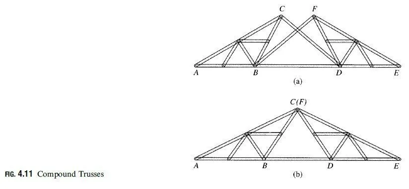
Compound trusses are constructed by connecting two or more simple trusses to form a single rigid body. To prevent any relative movement between the simple trusses, each truss must be connected to the other(s) by means of connections capable of transmitting at least three force components, all of which are neither parallel nor concurrent. Two examples of connection arrangements used to form compound trusses are shown in Fig. 4.11. In Fig. 4.11(a), two simple trusses ABC and DEF are connected by three members, BD;CD, and BF, which are nonparallel and nonconcurrent. Another type of connection arrangement is shown in Fig. 4.11(b). This involves connecting the two simple trusses ABC and DEF by a common joint C and a member BD. In order for the compound truss to be internally stable, the common joint C and joints B and D must not lie on a straight line. The relationship between the total number of members m and the total number of joints j for an internally stable compound truss remains the same as for the simple trusses. This relationship, which is given by Eq. (4.1), can be easily verified for the compound trusses shown in Fig. 4.11.
Internal Stability
Equation (4.1) expresses the requirement of the minimum number of members that a plane truss of j joints must contain if it is to be internally stable. If a plane truss contains m members and j joints, then if
m < 2j – 3 the truss is internally unstable
m => 2j – 3 the truss is internally stable
It is very important to realize that although the foregoing criterion for internal stability is necessary, it is not sufficient to ensure internal stability. A truss must not only contain enough members to satisfy the m => 2j – 3 condition, but the members must also be properly arranged to ensure rigidity of the entire truss. Recall from our discussion of simple and compound trusses that in a stable truss, each joint is connected to the rest of the structure by at least two nonparallel members, and each portion of the truss must be connected to the remainder of the truss by connections capable of transmitting at least three nonparallel and nonconcurrent force components.
Example 4.1
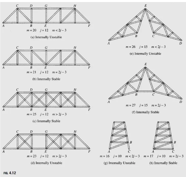
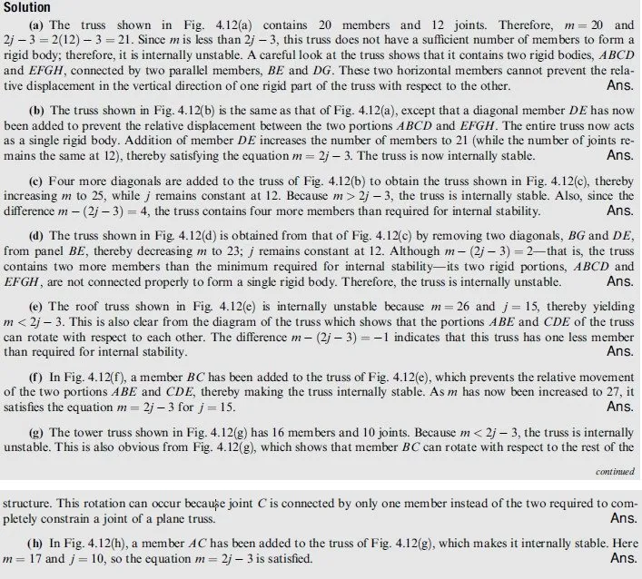
Classify each of the plane trusses shown in Fig. 4.12 as internally stable or unstable.


