The analysis of trusses is usually based on the following simplifying assumptions:
1. All members are connected only at their ends by frictionless hinges in plane trusses and by frictionless ball-and-socket joints in space trusses.
2. All loads and support reactions are applied only at the joints.
3. The centroidal axis of each member coincides with the line connecting the centers of the adjacent joints.
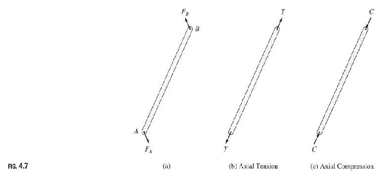
The reason for making these assumptions is to obtain an ideal truss, whose members are subjected only to axial forces. Since each member of an ideal truss is connected at its ends by frictionless hinges (assumption 1) with no loads applied between its ends (assumption 2), the member would be subjected to only two forces at its ends, as shown in Fig. 4.7(a). Since the member is in equilibrium, the resultant force and the resultant couple of the two forces FA and FB must be zero; that is, the forces must satisfy the three equations of equilibrium. From Fig. 4.7(a), we can see that in order for the resultant force of the two forces to be zero (∑Fx =0 and ∑Fy =0), the two forces must be equal in magnitude but with opposite senses. For their resultant couple to be also equal to zero (∑M =0), the two forces must be collinear that is, they must have the same line of action. Moreover, since the centroidal axis of each truss member is a straight line coinciding with the line connecting the centers of the adjacent joints (assumption 3), the member is not subjected to any bending moment or shear force and is either in axial tension (being elongated, as shown in Fig. 4.7(b)) or in axial compression (being shortened, as shown in Fig. 4.7(c)). Such member axial forces determined from the analysis of an ideal truss are called the primary forces.
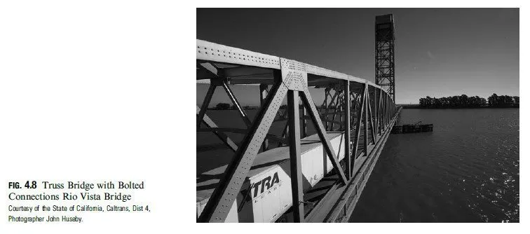
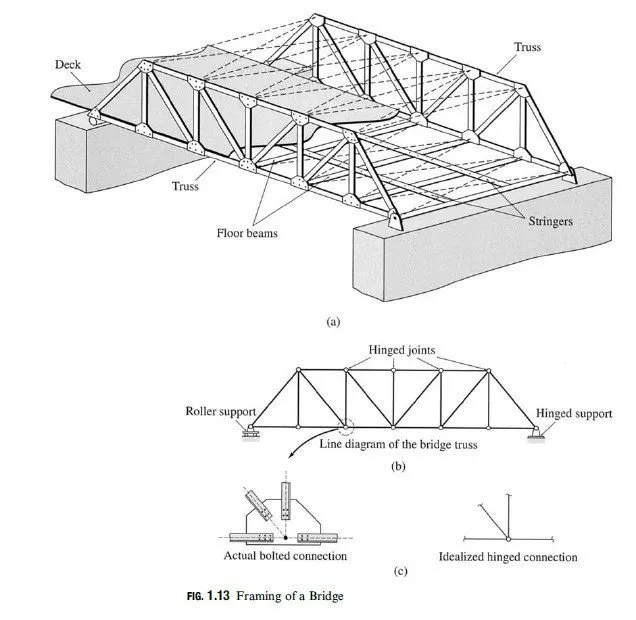
In real trusses, these idealizations are almost never completely realized. As stated previously, real trusses are constructed by connecting members to gusset plates by welded or bolted connections (Fig. 4.8). Some members of the truss may even be continuous at the joints. Furthermore, although the external loads are indeed transmitted to the trusses at joints by means of floor beams, purlins, and so on, the dead weights of the members are distributed along their lengths. The bending moments and shear and axial forces caused by these and other deviations from the aforementioned idealized conditions are commonly referred to as secondary forces. Although secondary forces cannot be eliminated, they can be substantially reduced in most trusses by using relatively slender members and by designing connections so that the centroidal axes of the members meeting at a joint are concurrent at a point (as shown in Fig. 1.13). The secondary forces in such trusses are small compared to the primary forces and are usually not considered in their designs. In this chapter, we focus only on primary forces. If large secondary forces are anticipated, the truss should be analyzed as a rigid frame using the methods presented in subsequent chapters.
