Historically, the first problems for impedances considering soil inertia were solved semianalytically for homogeneous half-space without the internal damping and for circular surface stamps. It turned out that horizontal impedances behaved more or less like pairs of springs and viscous dashpots (as mentioned above, in reality the dissipation of energy had completely different nature; mechanical energy was not converted in heat, as in dashpot, but??taken away by elastic waves). One more good news was that the impedance matrix appeared to be almost diagonal. Though non-diagonal terms coupling horizontal translation with rocking in the same vertical plane were non-zero ones, their squares were considerably less in module than products of the corresponding diagonal terms of the impedance matrix.
These two facts created a base for using the above mentioned soil springs and dashpots.
There are several variants of stiffness and dashpot parameters. You can see below a table 1
from ASCE4-98 [1] for circular base mats.
One more table of the same sort in the same standard [1] is given for rectangular base mats.
However, even for homogeneous half-space it turned out that vertical and angular impedances behaved differently from simple springs and dashpots. This can be seen in Fig.10, where the tabular impedances given by ASCE4-98 are compared to the wave solutions given by codes SASSI and CLASSI (number in the legend denotes number of finite elements along the side).
We understand now that the expressions given in the tables are just approximations for the real values. So, there cannot be exact or true expressions of this kind different variants exist.
The expressions from the tables look particularly strange for angular damping, where parameters of the upper structure participate. It is real absurd from the physical point of view: impedances cannot depend on the upper structure; soil just does not know what is above rigid stamp. This is not an error, as some colleagues think. This is an attempt to take values from the frequency-dependent curves at certain frequencies. These frequencies estimate the first natural frequencies of rigid structure on flexible soil, so they depend on structural inertial parameters. Surely, such expressions are approximate.
The conclusion is that frequency dependence of the impedances exists even for the homogeneous half-space and spoils the spring/dashpot models in the impedance method.
One more comment should be added here. If a package of horizontal layers is underlain by rigid rock, surface waves behave in a completely different manner than for homogeneous half-space. Instead of two surface waves (Love and Rayleigh ones) there exist an infinite number of surface waves. Each of these waves for low frequencies cannot take energy from the basement they are geometrically dissipating (even without internal soil damping), or locked. However, when frequency goes up, each of these waves one by one transforms from a locked wave into a running wave capable to take energy to the infinity. This behavior depends on soil geometry only, not on structure.
It means that in the frequency domain there exists a certain low-frequency range, where the whole soil foundation is locked. All the energy taken from the basement is only due to the internal damping. If there is no internal damping, complex impedances are completely real.
In practice internal soil damping is several percent, so impedances are almost real. After the first surface wave transforms into a running one, the soil foundation becomes unlocked wave damping appears. Then one by one other surface waves turn into running ones, increasing the integral damping in the soil-structure system. The impedance functions for the same soil, but underlain by rigid rock at depth 26 m, are shown on Fig.11. One can see locking phenomena looking at the imaginary parts of the impedances.
The conclusion here is that the frequency dependence of the impedances may be rather sophisticated depending on soil layering. The attempts to cover the variety of soils by number of homogeneous half-spaces with different properties (usually this is an approach for serial design of structures) may lead to mistakes: there is always a possibility that real layered soil will not be covered by a set of half-spaces (e.g. no half-space can reproduce the locking effects described above).
The additional problem with springs and dashpots arises when the integral stiffness is distributed over the contact surface Q. Physically in every point of Q there are no distributed angular loads impacting basement from the soil. So, only translational springs and dashpots are usually distributed over Q, and angular impedances are the results of these distributed translational springs. For a surface basement vertical distributed springs are responsible for rocking impedances, and horizontal springs are responsible for torsional impedance. The problem here is that all attempts to find the distribution shape for vertical springs to represent rocking impedances simultaneously with vertical one have failed. If fact, integral rocking stiffness obtained from distributed vertical springs is always less than actual rocking stiffness; on the contrary, integral rocking damping obtained from distributed vertical dashpots is always greater than the actual one. Physical reason of this mismatch is the interaction between different points through soil. Spring/dashpot model is local in nature: the response is determined by motion of this very point, and not neighbors. This is not physically true.
The author found a way to treat both problems at once. The idea is to work in the time domain using a platform model of Fig.5 with conventional springs and dashpots (lumped or distributed). Of course we get some platform impedances D(ω), different from wave impedances C(ω), but the idea is to tune the platform excitation Vb so to account for the difference between wave impedances and platform impedances. Six components of the platform excitation may be tuned to reproduce six components of response e.g., six components of the rigid base mats accelerations. Such an approach combines the calculations in the frequency domain (platform seismic input) with calculations in the time domain (final dynamic analysis of the platform model), that is why this method is called combined. Besides, this method is exact for rigid base mats only: the stiffer is a base mat, the more accurate are the results. That is why this method is also called asymptotic full name is combined asymptotic method (CAM) [22].
The last item to discuss in this part is practical tools to obtain impedances and seismic loads (or weightless base mats motions) in the frequency domain. At the moment the author uses one of two computer codes. For rigid surface basements on a horizontally-layered soil code CLASSI is the most appropriate. For the embedded basements with possible local breaks in horizontal layering code SASSI is used (SASSI can be used for surface base mats also, but is more sophisticated).
In both cases formula (3) is a basic equation for impedances, and the dynamic stiffness matrix G0 linking set of nodes in the infinite soil is a key issue (the second matrix Gint is absent for surface basement in CLASSI and easily obtained by FEM for the embedded basement in SASSI). To get G0, they first obtain a dynamic flexibility matrix, describing displacements due to the unit forces (this is a Greens function). Here is a difference between two codes.
Professor J.Luco managed [7] to develop Greens function analytically for the case of surface load and surface response node in horizontally-layered soil in the frequency domain. Then contact surface Q was covered with number of rectangular elements of different shapes.
Loads were applied in the centers of each element one by one; response displacements were obtained in the centers of each element for each load. The additional convenience was that for the horizontally layered soil one can shift the loaded node and the response node horizontally, and the link between them stays the same. So, in fact one needs Greens functions only for a single loaded node and for the response nodes placed at a distance from the loaded node within maximal size of the mat. Zero (for vertical load) and first (for horizontal load) Fourier terms describe the displacement field along angular cylindrical coordinate, enabling to store Greens functions only along 1D radial line. Thus, it is not very time-consuming to obtain Greens function (it is done in a separate module Green) and to use it in order to obtain the full flexibility matrix (in separate module Claff). Then this full flexibility matrix is turned into a full stiffness matrix G0. Finally G0 is condensed to the 6 x 6 impedance matrix C. The whole procedure is repeated for each frequency of the prescribed set. For a surface rigid basement and vertical waves there is no separate problem to find the load matrix B in equation (4): kinematical interaction does not change control motion, so B consists of the first three columns of C. This was a brief description of CLASSI ideology.
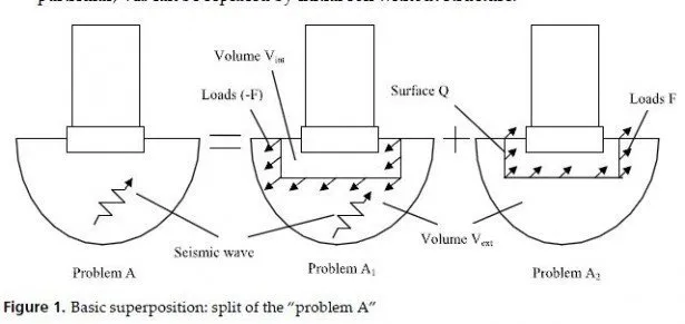
J.Lysmer for the same problem (but for the embedded loaded and response nodes) used direct approach described above. He made Vint a cylindrical column, with just a single element per radius. The bottom of this column was placed on a homogeneous half-space, so a dashpot was put there in each of three directions. Lateral boundaries were of Waas type.
Loads were applied to the nodes at the vertical axis of cylinder. The response nodes were either at the same axis or out of the cylinder (for regular mesh the radius of cylinder was set equal to 0.9 of mesh size). In the first case, the response displacements were obtained from the FEM problem. In the second case the solution of the FEM problem gave the displacements of the nodes at the lateral boundary. Then the displacements in the whole infinite volume Vext were obtained using homogeneous wave fields in cylindrical coordinates described above (with Hankels functions along radius). Like in CLASSI, horizontal shift of the loaded and response nodes is allowed in the horizontally-layered soil.
So only a single cylinder has to be studied. Like in CLASSI, it is done in a separate module (in SASSI it is called POINT). After a flexibility matrix for a set of interacting nodes covering Vint is obtained, it is turned into a stiffness matrix G0. This matrix may be condensed into a part of the impedance matrix like in CLASSI (another part comes from Gint).
However, one can instead return to the problem A2 without condensation (e.g., for flexible basement or locally modified soil around the basement). Bottom of surface Q is placed not on the rock, as it was in Fig.3, but where it is convenient (usually at the bottom of the modified soil volume, if any, or at the bottom of the basement). This approach may be called a combined one, because the direct approach is used to get Greens function only; further on, the impedance approach (extended for flexible underground volume Vint) is applied. The problem of axial symmetry has gone both in CLASSI and in SASSI: though basic problem in Green or in POINT has an axisymmetric geometry and is solved in cylindrical coordinates, the interaction nodes set may be arbitrary in shape.
Another problem for SASSI is with flexible underlying half-space: Waas boundaries were developed for rigid half-space at the bottom only. Lysmers team found a brilliant approximate solution. Energy for a cylinder in POINT is taken down in the half-space by vertical body waves (modeled by dashpots, see above) and by surface Rayleigh waves in the flexible half-space. These Rayleigh waves in the frequency domain have a certain depth where the wave displacements are close to zero. One can put rigid bottom at that very depth without spoiling the response in the upper part of the soil. The problem is that this depth is frequency-dependent: so, the model in POINT becomes non-physical. However, transmitting boundaries, as we remember, were developed by G.Waas in the frequency domain, so the problem is solved frequency by frequency. Hence, one can change the depth of rigid boundary at the bottom of the model according to the frequency change. In SASSI it is done automatically: soil model in POINT consists of the upper part with fixed layers, and of the lower part with frequency-dependent layers.
For surface basements one can compare the impedances given by SASSI and CLASSI. In the frequency range below 15 Hz the results are very close to each other. Examples were shown above (see Fig.10).


