Since composite slabs span in one direction only, their ability to carry masonry partition walls or other heavy local loads is limited. Rules are given in Eurocode 4 (and in the British code) for widths of composite slabs effective for bending and vertical shear resistance, for point and line loads, as functions of the shape and size of the loaded area. These are based on a mixture of simplified analyses, test data, and experience.
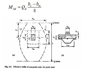
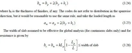
They are illustrated here for a rectangular loaded area ap by bp, with its centre distance Lp from the nearer of a slab of span L, as shown in Fig.3.6(a). The load may be assumed to be distributed over a width bm, defined by lines at 45 (Fig.3.6(b)), where
where k is taken as 2 for bending and longitudinal shear (except for interior spans of continuous
slabs, where k=1.33) and as 1 for vertical shear.
For a simply-supported slab and point load Qd, the sagging moment per unit width of slab on
line AD in Fig.3.6(a) is thus

which is a maximum when Lp = L / 2
The variation of bc with Lp is shown in Fig.3.6(a). The load is assumed to be uniformly distributed along line BC. Whereas the resistance is distributed along line AD, so there is sagging transverse bending under the load. The maximum sagging bending moment is at E, and is given by

The sheeting has no tensile strength in this direction, because the corrugations can open out, so bottom reinforcement (Fig.3.6(b)) must be provided. It is suggested that this reinforcement should be spread over the length am given by equation (3.25).
It is stated in Eurocode 4 that where transverse reinforcement is provided with a cross-sectional area of at least 0.2% of the area of concrete above the ribs of the sheeting, no calculations are needed for characteristic concentrated loads not exceeding 7.5kN. Calculation in Section 3.4 show that for the slab considered there, more than 0.2% appears to be necessary, so in that case the preceding rules are more conservative than the concession.
Vertical shear should be checked along a line such as FG, when Lp is such that GF is above the edge of the flange of the steel beam. It rarely governs design.


