Composite slabs have for several decades been the most widely used method of suspended floor construction for steel-framed buildings in North America. Within the last twenty years there have been many advances in design procedures, and a wide range of profiled sheetings has become available in Europe. The British Standard for the design of composite floors first appeared in 1982, and there are preliminary Eurocodes for design of both the sheeting alone and the composite slab. The steel sheeting has to support not only the wet concrete for the floor slab, but other loads that are imposed during concreting. These may include the heaping of concrete and pipeline or pumping loads. The minimum characteristic value given for these in Eurocode 4 is 1.5 kN/m3 on any area 3 m by 3 m, plus 0.75 kN/m2 on the remaining area.
Profiled steel sheeting
The sheeting is very thin, for economic reasons; usually between 0.8mm and 1.2mm. it has to be galvanized to resist corrosion, and this adds about 0.04mm to the overall thickness. It is specified in Eurocode 3. Part 1.3 that where design is based on the nominal thickness of the steel, the sheet must have at least 95% of that thickness but it is not a simple matter for the user to check this! The sheets are pressed or cold rolled, and are typically about 1m wide and up to 6 m long. They are designed to span in the longitudinal direction only. For many years, sheets typically 50 mm deep, and the limiting span was about 3 m. The cost of propping the sheets during concreting led to the development of deeper profiles; but design of composite slabs is still often governed by a limit on deflection. There is then no advantage in using a high-yield steel, so most sheeting in the UK is of mild steel.
The local buckling stress of a flat panel within sheeting should ideally exceed its yield strength:
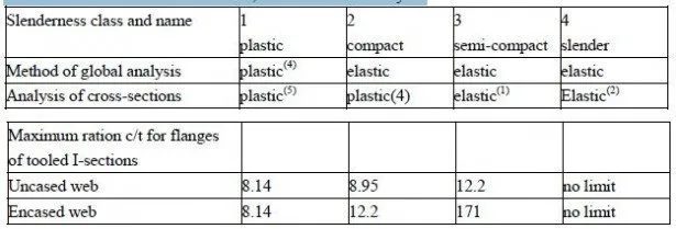
but this requires breadth/thickness ratios of less than about 35. Modern profiles have local stiffening ribs, but it is difficult to achieve slendernesses less that about 50, so that for flexure, the sections are in Class 4 (i.e. the buckling stress is below the yield stress). Calculation of the resistance to bending then becomes complex, and involves trial and error.
The specified or nominal yield strength is that of the flat sheet from which the sheeting is made.
In the finished product, the yield strength is higher at every bend and corner, because of work hardening.
To enable it to fulfill its second role, as reinforcement for the concrete slab, dimples are pressed into the surface of the sheeting, to act as shear connectors. These dimpled areas may not be fully effective in resisting longitudinal stress, so both they and the local buckling reduce the second moment of area (I) of the sheeting to below the value calculated for the gross steel section.
For these reasons, manufacturers commission tests on prototype sheets, and provide designers either with test-based values of resistance and stiffness, or with safe-load tables calculated from those values.
Design of composite slab
The cross-sectional area of steel sheeting that is needed for the construction phase often provides more than enough bottom reinforcement for the composite slab. It is then usual to design the slabs as simply-supported. The concrete is of course continuous over the supporting beams, and alternate sheets may be as well (e.g. if 6m sheets are used for a succession of 3 m spans).
These simply-supported slabs require top longitudinal reinforcement at their supports, to control the widths of cracks. The amount is specified in Eurocode 4 as 0.2% of the cross-sectional area of concrete above the steel ribs for unpropped construction, and 0.4% for propped construction.
Long-span slabs are sometimes designed as continuous over their supports. They are analysed as described in Section 4.7. Several action effects that have to be considered in the design of composite slabs are now considered. The methods are illustrated by the worked example in Section 3.4.


