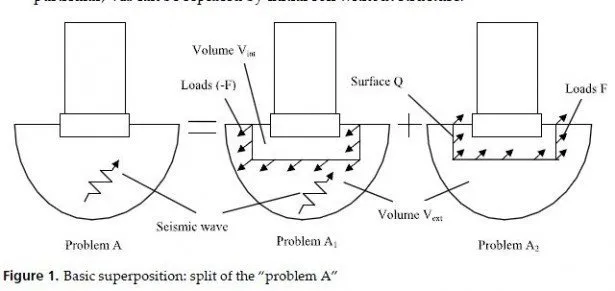
If we presume the rigidity of the soil-structure contact surface and place surface Q in Fig.1 right at this surface, we get six degrees of freedom for Q. Corresponding forces F in problem A2 are condensed to sixcomponent integral forces, loading the immovable base mat during seismic excitation. In addition, when the mat moves, Vext impacts the moving base mat by response forces set by dynamic stiffness matrix 6 x 6. This matrix is a linear operators matrix in the time domain for linear soil (soil in Vext was linear from the very beginning). In the frequency domain it becomes complex frequency dependent matrix called impedance matrix. That is why the whole approach is called the impedance one.
Impedances can be estimated in the field experiments with stamps excited by unbalanced rotors. They were the first parameters of the soil flexibility in the early times of SSI (when machinery base mats were analyzed).
Let Rj(x) be real rigid?? vector displacements field of the contact surface Q, when one of six general coordinates of the surface Q (coordinate number j) gets a unit displacement. If some contact vector forces F(x) act over Q, the condensed integral general force along coordinate j is given by

Scalar product of two 3D vectors is used under the integral (2). If G0 is the dynamic stiffness operator in the initial soil, and Q moves by unit along the general coordinate k, then the displacement field at Q is described by Rk(x), and response forces impacting Q in the initial soil are given by G0 Rk. However, for the embedded Q these total forces consist of the part Fk(x) impacting Q from Vext and another part impacting Q from Vint (see Fig.2). If Gint is the analogue of G0 for the finite volume Vint, then Fk=(G0-Gint) Rk. In the frequency domain all linear operators become matrices. The impedance Cjk, meaning the condensed force acting from Vext to Q along coordinate j in response to the unit rigid displacement of Q along coordinate k is then given by

Double integration in (3) reflects the fact that G provides the response forces in the node x due to the displacements in the node y.
The next step is to condense load F over rigid surface Q. If Uk(x) is a transfer function from the control motion along coordinate k to the free-field wave in problem B, then in the frequency domain the transfer function Bjk to the condensed load along coordinate j according to (1) is given by
![]()
If U0 is a control motion of a certain point in problem B (generally multi-component one, though usually only three-component one), then the condensed total forces (not just F!) acting from the soil to the basement are given by
![]()
Here Ub(ω) is a six-component motion of the rigid base mat (i.e., soil-structure contact surface Q), C(ω) is 6 x 6 impedance matrix, B(ω) is usually 6 x 3 seismic loading matrix.
The important particular case is a surface basement then Vint goes and Gint in right-hand part of (3) goes as well. If in addition we presume Uk(y)=Rk(y)=1, k=1,2,3 (it means that the whole future contact surface Q in problem B has no seismic rotations and has the same translations as the control point; this is the case for vertically propagating seismic body waves in the horizontally-layered media), then matrix B is composed of the first three columns of matrix C.
Let K(ω) and M be stiffness and mass matrices of the structure without soil foundation (K may be complex to account for the structural internal damping), and let Us(ω) be absolute displacements of structure in the frequency domain. Then seismic motion in the soilstructure system is described by the equation
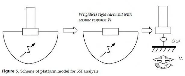
Now let us imagine the same rigid contact surface on the same soil with the same seismic excitation, with the only difference: structure with rigid basement is weightless. The righthand part of (7) will stay in place; in the left-hand part only C(ω) represents dynamic stiffness, because weightless structure is moving rigidly together with the basement, and no forces occur due to K. Let Vb(ω) be the response of the rigid weightless basement (instead of Ub(ω) for massive structure:

This equation is of great importance because it describes the so-called platform model, shown in Fig.5. Rigid platform is excited by a prescribed motion Vb(ω). Structural model is resting on a soil support with prescribed stiffness described by the impedance matrix C(ω).
One should clearly understand that this platform is not physical: in the real world there is no rigid platform having such a motion. Often they try to imagine some hard rock somewhere there is a mistake! This model is applicable, for example, for homogeneous half-space no rock is present anywhere. In fact, platform model is just a mechanical analogue of the soil-structure model in terms of the structural response.
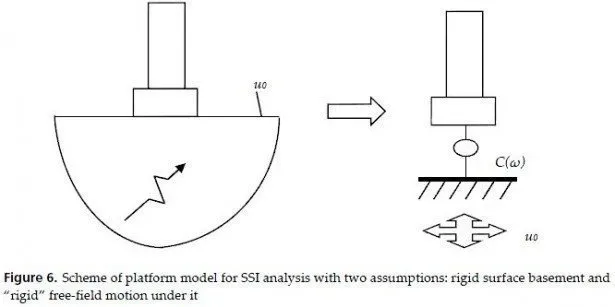
Let us work a little with this platform model. In the popular particular case with two assumptions mentioned above (i.e. surface rigid basement and vertical seismic waves in the??horizontally layered medium) weightless rigid base mat will move exactly with control accelerations from free field. In other words Vb=U0. This case is shown in Fig.6.
If any of the two assumptions is not valid, one has to solve a special problem to obtain Vb it is called kinematic soil-structure interaction problem. For embedded basements it is allowed to neglect the embedment depth if it is less then 30% of the effective radius of the mat. In this case upper layers of the soil foundation are just withdrawn from the soil model.
This may sometimes cause some changes in the free-field motion.
However, even for the surface basements the second assumption is not always correct. If the free-field motion U0 of the soil surface is not rigid over Q, the rigid basements response is somehow averaging it over the mat; in this case the translational response Vb may be less than control motion U0 in a single node. On the other hand, the variability of horizontal U0 under the mat may cause torsion in Vb, and the variability of vertical U0 under the mat may cause rocking in Vb.
The second part of the problem (i.e. the dynamic analysis of the platform model from Fig.5) is called inertial soil-structure interaction problem. Often they solve it putting the coordinate system on the platform (thus, coming to the fixed platform, but instead introducing inertial forces impacting all the masses of structure).
One can easily see that conventional structural seismic response without SSI is obtained from the platform model as well. The difference with Fig.5 is only in the soil support and in the platform excitation. If we make soil stiffer and stiffer, Vb comes closer and closer to U0;
soil support becomes stiff, and this difference also goes. So, we get a model without SSI as a limit case of the platform model with SSI with extremely hard soil.
Platform model can be extended to the case of several buildings having common soil foundation. The main limitations are the same rigid basements and linear foundation/contact. Note that generally (with kinematic interaction on Fig.5) no requirements are made for soil layering, embedment depth, shape of the underground part, etc.
The alternative form of the platform model uses fixed platform, and dynamic loads are directly applied to the rigid basement. These loads correspond to the right-hand parts of (9), (8) or (7).
Platform model is convenient to work with in the frequency domain. Huge matrix [K-ω2M] can be condensed to the rigid base mat using natural modes and natural frequencies of the fixed-base structure [20]. As a result, we get M(ω) the dynamic inertia complex frequency-dependent matrix 6 x 6 similar in size to C(ω). Equation (7) turns to ![]()
It is easily solved, because maximal size is 6. The response in the time domain is further obtained using Fast Fourier Transform (FFT). For multiple-base structure the dynamic stiffness is condensed in a somewhat different way [21], though the size of the resulting matrix is still 6 x (number of base mats).
However, usually engineers prefer the time domain for the dynamic problems. Platform model of Fig.5 and equation (9) can be transferred to the time domain. Structural part is transferred easily. Kinematic excitation Vb can be also transferred to the time domain using FFT. The only problem is to transfer to the time domain impedance matrix C(ω).
The most popular variant is just a set of six springs and six viscous dashpots (one spring and one dashpot along each of six coordinates). In the frequency domain an ordinary spring corresponds to the real frequency-independent impedance, and viscous dashpot corresponds to the frequency-linear purely imaginary impedance. So, matrix C(ω) corresponding to such a set of springs/dashpots will be diagonal complex matrix 6 x 6 with frequency-independent real parts and frequency-linear imaginary parts. Is it realistic for real-world soil foundations? This question deserves special discussion. But before we enter it, let us consider a very simple example, illustrating methodology of SSI problem as a whole and two basic different approaches to this problem (i.e., direct and impedance ones) described above.

