8.4 Transformations between ellipsoids
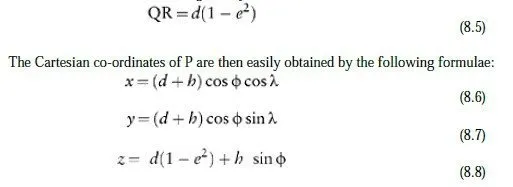
Because points on the earths surface can be expressed in terms of different Cartesian/ellipsoidal systems, there is often a need to convert a points co-ordinates from one system (A, say) to another (B). This is particularly the case when GPS information (which is measured in the WGS84 system, or perhaps in ETRS89) needs to be combined with information defined in terms of a local ellipsoid, such as Airy 1830. First, the (Φ , λ, h) (i.e. latitude, longitude, height) co-ordinates of the point in ellipsoidal system A are converted into the corresponding (x, y, z) co-ordinates, as shown in Figure 8.1. This requires the shape parameters of the ellipse in question, which are normally given in terms of the semi-major axis, a, and the reciprocal of flattening,7 r. The semi-minor axis, b, can then be obtained (if required) from the expression:
![]()
6 Note that:
7 The flattening, f, of an ellipse is defined by: and also that the distance QR is given by:
The next step is to transform the (x, y, z) co-ordinates of P in system A into corresponding co-ordinates in system B, which we will term (x², y², z²). This transformation consists of a translation and a rotation to accommodate the fact that the two ellipsoids have different centres and orientations with respect to each other. Sometimes, though, a scale factor is also defined as part of the transform. This is fundamentally illogical, since 1 m in system A should equal 1 m in system B, albeit in a different orientation. The purpose, however, is to allow for the fact that the sets of fixed markers which still define some ellipsoids are not the exact distance apart that they have been defined to be, due to the difficulty of measuring accurate distances at the time when the size of the ellipse and the co-ordinates of the markers were defined. Any change in orientation in three dimensions can be thought of as a rotation of a given magnitude about an axis lying in a given direction. The vector re can be used to define this rotation, with the unit vector e=[ex ey ez]T defining the direction of the axis and r the magnitude of the rotation in radians. The scalar values of rex, rey and rez are the so-called Euler angles, which define the change in orientation and are more simply written as rx, ry and rz. The transformation caused to the point (x, y, z) by a rotation through an angle r about the axis e passing through the origin, is given by:
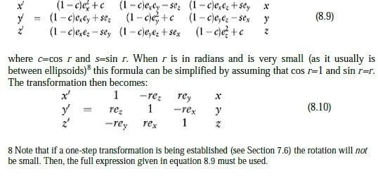
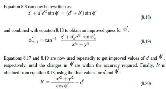
The origin shift t and the scale factor s (which is usually expressed as a fractional increase or decrease, so must have 1 added to it) can now be incorporated into the transformation. Doing this, and substituting the simpler format for the Euler angles gives:
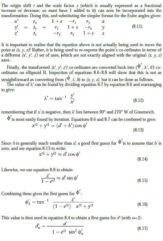
A worked example of this process is given in Appendix C. The following points are useful when applying the transform: 1 Be sure to use the given parameters correctly in equation 8.11. The values of rx, ry and rz must be in radians, and the value of 1+s should be very close to unity. (The given angles are often quoted in seconds of arc, and the scale factor is often quoted in parts per million.) 2 Remember that if (say) millimetre precision is required from the conversion, this is about one part in 1010, compared with the (x, y, z) co-ordinates of the point. All calculations must be done to ten significant figures, and double precision arithmetic should be used in computer programs. 3 It is useful to have at least one point whose position is already known in both systems, to test that the transform has been set up correctly before further points are transformed. 4 The reverse transform can be obtained by changing the signs of the shifts, rotations and scale factor quoted for the forward transform. Note that this reverse transform is not the exact inverse of the original transform matrix, so any transformed points will not return exactly to their original positions; the resulting position errors will be of the order of δ2/RE, where δ is the movement caused by the rotational part of the transform and RE the earths radius (6.38×10⁶ m). This is because the transform matrix is the approximate version shown in equation 8.10, rather than the exact (and conformal) version given in equation 8.9. The resulting errors are usually negligible, but might become significant for Euler angles larger than one second.
8.5 ETRS89 and the International Terrestrial Reference System
A common application of ellipsoid transformations is the conversion of co-ordinates between the realisation of WGS84 on a particular continent (ETRS89 in Europe) and the International Terrestrial Reference System (ITRS), which is the definitive realisation of WGS84 on the earths surface. ITRS is a method for generating reference frames by means of a best fit to a number of points around the world, but since these points lie on different continents, they are continually moving with respect to one another by quite substantial amounts. Applying the method thus gives rise to a series of so-called International Terrestrial Reference Frames (ITRFs), which are published from time to time by the International Earth Rotation Service (IERS). At the time of writing, the most recent one is ITRS2000. ETRS89 was based on the accepted ITRS co-ordinates of the ETRF stations in Europe at the start of 1989, but then slightly amended by subsequent and more accurate remeasurement of the relative positions of the stations. Since 1989, the drift of the Eurasian tectonic plate has caused the two systems to move steadily further apart. As a result, the official transform between ETRS89 and ITRS2000 quoted by IERS has a time element built into it. The time which must be used is the period (in years) between 1 January 1989 and the date for which the ITRS co-ordinates are required. Applying this transform allows surveyors from different continents to combine their data on a common best-fit framework, at any given point in time. The parameters for this transform, together with the dimensions of several commonly used ellipsoids, are given in Appendix A.