Space trusses, because of their shape, arrangement of members, or applied loading, cannot be subdivided into plane trusses for the purposes of analysis and must, therefore, be analyzed as three-dimensional structures subjected to three-dimensional force systems. As stated in Section 4.1, to simplify the analysis of space trusses, it is assumed that the truss members are connected at their ends by frictionless ball-and-socket joints, all external loads and reactions are applied only at the joints, and the centroidal axis of each member coincides with the line connecting the centers of the adjacent joints. Because of these simplifying assumptions, the members of space trusses can be treated as axial force members.
The simplest internally stable (or rigid) space truss can be formed by connecting six members at their ends by four ball-and-socket joints to form a tetrahedron, as shown in Fig. 4.28(a). This tetrahedron truss may be considered as the basic space truss element. It should be realized that this basic space truss is internally stable in the sense that it is a threedimensional rigid body that will not change its shape under a general three-dimensional loading applied at its joints. The basic truss ABCD of Fig. 4.28(a) can be enlarged by attaching three new members, BE;CE, and DE, to three of the existing joints B;C, and D, and by connecting them to form a new joint E, as depicted in Fig. 4.28(b). As long as the new joint E does not lie in the plane containing the existing joints B;C,
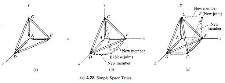
and D, the new enlarged truss will be internally stable. The truss can be further enlarged by repeating the same procedure (as shown in Fig. 4.28(c)) as many times as desired. Trusses constructed by this procedure are termed simple space trusses.
A simple space truss is formed by enlarging the basic tetrahedron element containing six members and four joints by adding three additional members for each additional joint, so the total number of members min a simple space truss is given by
m = 6 + 3 (j-4) = 3j – 6 [eq 4.5]
in which j =total number of joints (including those attached to the supports).
Reactions
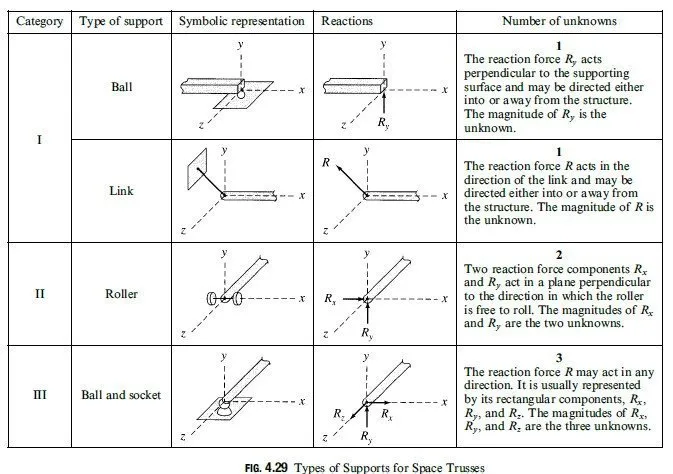
The types of supports commonly used for space trusses are depicted in Fig. 4.29. The number and directions of the reaction forces that a support may exert on the truss depend on the number and directions of the translations it prevents.
As suggested in Section 3.1, in order for an internally stable space structure to be in equilibrium under a general system of threedimensional forces, it must be supported by at least six reactions that satisfy the six equations of equilibrium (Eq. (3.1)):

Because there are only six equilibrium equations, they cannot be used to determine more than six reactions. Thus, an internally stable space structure that is statically determinate externally must be supported by exactly six reactions. If a space structure is supported by more than six reactions, then all the reactions cannot be determined from the six equilibrium equations, and such a structure is termed statically indeterminate externally. Conversely, if a space structure is supported by fewer than six reactions, the reactions are not su°cient to prevent all possible movements of the structure in three-dimensional space, and such a structure is referred to as statically unstable externally. Thus, if
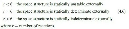
As in the case of plane structures discussed in the previous chapter, the conditions for static determinacy and indeterminacy, as given in Eq. (4.6), are necessary but not sufficient. In order for a space structure to be geometrically stable externally, the reactions must be properly arranged so that they can prevent translations in the directions of, as well as rotations about, each of the three coordinate axes. For example, if the lines of action of all the reactions of a space structure are either parallel or intersect a common axis, the structure would be geometrically unstable.
Static Determinacy, Indeterminacy, and Instability
If a space truss contains m members and is supported by r external reactions, then for its analysis we need to determine a total of m þ r unknown forces. Since the truss is in equilibrium, each of its joints must also be in equilibrium. At each joint, the internal and external forces form a three-dimensional concurrent force system that must satisfy the three equations of equilibrium, ∑Fx = 0, ∑Fy= 0, and ∑Fz = 0. Therefore, if the truss contains j joints, the total number of equilibrium equations available is 3j. If m + r = 3j, all the unknowns can be determined by solving the 3j equations of equilibrium, and the truss is statically determinate.
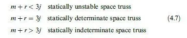
Space trusses containing more unknowns than the available equilibrium equations (m+r>3j) are statically indeterminate, and those with fewer unknowns than the equilibrium equations (m+r<3j) are statically unstable. Thus, the conditions of static instability, determinacy, and indeterminacy of space trusses can be summarized as follows:
In order for the criteria for static determinacy and indeterminacy, as given by Eq. (4.7), to be valid, the truss must be stable and act as a single rigid body, under a general three-dimensional system of loads, when attached to the supports.
Analysis of Member Forces
The two methods for analysis of plane trusses discussed in Sections 4.5 and 4.6 can be extended to the analysis of space trusses. The method of joints essentially remains the same, except that three equilibrium equations (∑Fx = 0, ∑Fy = 0, and ∑Fz = 0) must now be satisfied at each joint of the space truss. Since the three equilibrium equations cannot be used to determine more than three unknown forces, the analysis is started at a joint that has a maximum of three unknown forces (which must not be coplanar) acting on it. The three unknowns are determined by applying the three equations of equilibrium. We then proceed from joint to joint, computing three or fewer unknown forces at each subsequent joint, until all the desired forces have been determined.
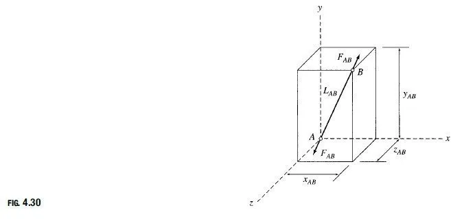
Since it is di°cult to visualize the orientations of inclined members in three-dimensional space, it is usually convenient to express the rectangular components of forces in such members in terms of the projections of member lengths in the x; y, and z directions. Consider a member AB of a space truss, as shown in Fig. 4.30. The projections of its length LAB in the x; y, and z directions are xAB; yAB, and zAB, respectively, as shown, with
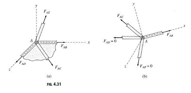
1. If all but one of the members connected to a joint lie in a single plane and no external loads or reactions are applied to the joint, then the force in the member that is not coplanar is zero.
2. If all but two of the members connected to a joint have zero force and no external loads or reactions are applied to the joint, then unless the two remaining members are collinear, the force in each of them is also zero.
The first type of arrangement is shown in Fig. 4.31(a). It consists of four members AB;AC;AD, and AE connected to a joint A. Of these, AB;AC, and AD lie in the xz plane, whereas member AE does not. Note that no external loads or reactions are applied to joint A. It should be obvious that in order to satisfy the equilibrium equation ∑Fy = 0, the y component of FAE must be zero, and therefore ∑AE = 0.
The second type of arrangement is shown in Fig. 4.31(b). It consists of four members AB;AC;AD, and AE connected to a joint A, of which AD and AE are zero-force members, as shown. Note that no external loads or reactions are applied to the joint. By choosing the orientation of the x axis in the direction of member AB, we can see that the equilibrium equations∑Fy = 0 and ∑Fz = 0 can be satisfied only if FAC = 0. Because the x component of FAC is zero, the equation ∑Fx = 0 is satisfied only if FAB is also zero.
As in the case of plane trusses, the method of sections can be employed for determining forces in specific members of space trusses. An imaginary section is passed through the truss, cutting the members whose forces are desired. The desired member forces are then calculated by applying the six equations of equilibrium (Eq. (3.1)) to one of the two portions of the truss. No more than six unknown forces can be determined from the six equilibrium equations, so a section is generally chosen that does not pass through more than six members with unknown forces.
Because of the considerable amount of computational efort involved, the analysis of space trusses is performed today on computers. However, it is important to analyze at least a few relatively small space trusses manually to gain an understanding of the basic concepts involved in the analysis of such structures.
Example 4.12
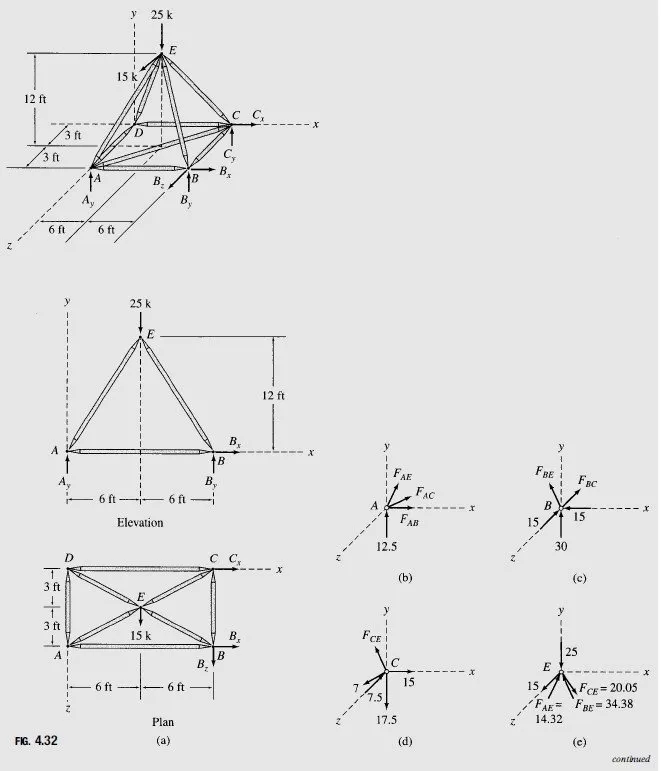
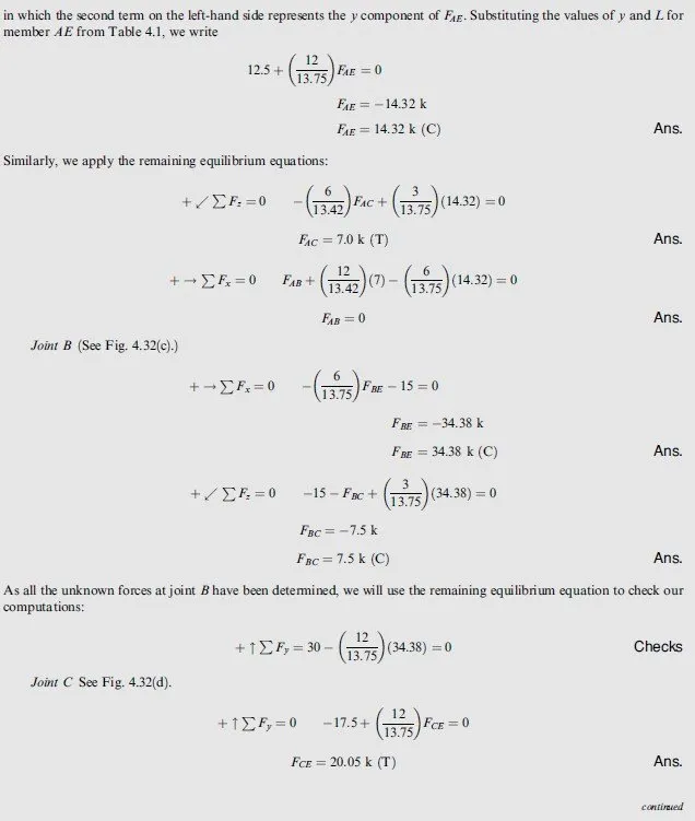
Determine the reactions at the supports and the force in each member of the space truss shown in Fig. 4.32(a).
Solution
Static Determinacy The truss contains 9 members and 5 joints and is supported by 6 reactions. Because m+r=3j and the reactions and the members of the truss are properly arranged, it is statically determinate.
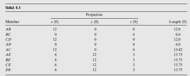
Member Projections The projections of the truss members in the x; y, and z directions, as obtained from Fig. 4.32(a), as well as their lengths computed from these projections, are tabulated in Table 4.1.
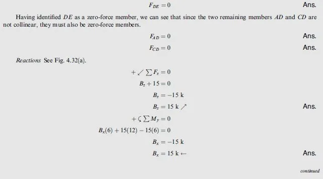
Zero-Force Members It can be seen from Fig. 4.32(a) that at joint D, three members, AD;CD, and DE, are connected. Of these members, AD and CD lie in the same ðxzà plane, whereas DE does not. Since no external loads or reactions are applied at the joint, member DE is a zero-force member.