Example 4.11
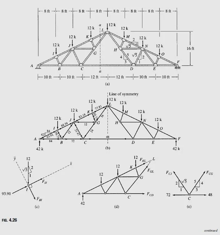
Determine the force in each member of the Fink truss shown in Fig. 4.26(a).
Solution
The Fink truss shown in Fig. 4.26(a) is a compound truss formed by connecting two simple trusses, ACL and DFL, by a common joint L and a member CD.
Symmetry Since the geometry of the truss and the applied loading are symmetrical about the center line of the truss (shown in Fig. 4.26(b)), its member forces will also be symmetrical with respect to the line of symmetry. It is, therefore, su°cient to determine member forces in only one-half of the truss. The member forces determined here for the left half of the truss are shown in Fig. 4.26(b). The forces in the right half can be obtained from the consideration of symmetry; for example, the force in member MN is equal to that in member JK, and so forth. The reader is urged to verify this by computing a few member forces in the right half of the truss.