Background
In design, account must be taken of the random nature of loading, the variability of materials, and the defects that occur in construction, to reduce the probability of unserviceability or failure of the structure during its design life to an acceptably low level. Extensive study of this subject since about 1950 has led to the incorporation of the older safety state design philosophy. Its first important application in Great Britain was in 1972, in CP 110, the structural use of concrete. All recent British and most international codes of practice for the design of structures now use it.
Work on international codes began after the Second World War, first on concrete structures and the on steel structures. A committee for composite structures, set up in 1971, prepared the Model Code of 1981.(7) Soon after January 1993 had been set as the target date for the completion of the Common Market in Europe, the Commission of the European Communities began (in 1982) to support work on documents now known as Eurocodes. It acts for the twelve countries of the European Union (formerly the EEC). In 1990, the seven countries of the European Free Trade Area (ETA) joined in, and responsibility for managing the work was transferred to the Comite Europeen Normalisation (CEN). This is an association of the national standards institutions of the 19 countries, which extend from Iceland and Finland in the north to Portugal and Greece in the south. It is now planned to prepare nine Eurocodes with a total of over 50 Parts. Each is published first as a preliminary standard (ENV), accompanied in each country by a National Application Document. All of the Eurocodes relevant to this volume are or soon will be at this stage. They are as follows:
Eurocode 1: Part 1, Basis of design; (8)
Eurocode 1: Basis of design, and actions, Part 2, General rules and gravity and impressed loads, snow, and fire; (9)
Eurocode 2: Part 1.1, Design of concrete structures; General rules and rules for buildings; (10)
Eurocode 3: Part 1.1, Design of steel structures; General rules and rules for buildings; (11)
Eurocode 4: Part 1.1, Design of composite steel and concrete structures; General rules and rules for buildings; (12)
Eurocode 4: Part 1.2, Structural fire design. (13)
At the end of its ENV period of three years, each Part of a Eurocode is revised, and will then be published as an EN (European standard), so the EN versions of the Parts listed above should appear from 1998 onwards. It is the intention that a few years later all relevant national codes in the 19 countries will be withdrawn from use.
The current British code that is most relevant to this volume is BS 5950: Part 3: Section 3.1: 1990.(14) It has much in common with Eurocode 4: Part 1.1, because the two were developed in parallel. The design philosophy, terminology, and notations of the Eurocodes have been harmonized to a greater extent than those of the current British codes, so it is convenient generallyto follow the Eurocodes in this volume. Eurocode 4: Part 1.1 will be cited simply as Eurocode 4 or EC4, and reference will be made to significant differences from BS 5950. This volume is intended to be self-contained, and to provide an introduction to its subject. Those who use Eurocode 4 in professional practice may need to refer to the relevant Handbook. (15)
Limit state design philosophy
Actions
Parts 1.1 of Eurocodes 2, 3 and 4 each have a Chapter 2, Basis of design, in which the
definitions, classifications, and principles of limit state design are set out in detail, with emphasis on design of structures for buildings. Much of these chapters will eventually be superseded by Eurocode 1: Part 1, where the scope is being extended to include bridges, towers, masts, silos and tanks, foundations, etc.
The word actions in the title of Eurocode 1: Part 2 does not appear in British codes. Actions are classified as * Direct actions (forces or loads applied to the structure), or
* Indirect actions (deformations imposed on the structure, for example by settlement of
foundations, change of temperature, or shrinkage of concrete).
Actions thus has a wider meaning than loads. Similarly, the Eurocode term effects of actions has a wider meaning than stress resultant, because it includes stresses, strains, deformations, crack widths, etc., as well as bending moments, shear forces, etc. The Eurocode term for stress resultant is internal force or moment.
The scope of the following introduction to limit state design is limited to that of the design
examples in this volume. There are two classes of limit states:
* Ultimate, which are associated with structural failure; and * Serviceability, such as excessive deformation, vibration, or width of cracks in concrete.
There are three types of design situation:
* persistent, corresponding to normal use;
* transient, for example, during construction; and * accidental, such as fire or earthquake.
There are three main types of action:
* Permanent (G), such as self-weight of a structure, sometimes called dead load;
* Variable (Q), such as imposed, wind or snow load, sometimes called live load; and * Accidental (A), such as impact from a vehicle.
The spatial variation of an action is either:
* Fixed (typical of permanent actions); or * Free (typical of other actions), and meaning that the action may occur over only a part of the area of length concerned.
Permanent actions are represented (and specified) by a characteristic value. GK Characteristic implies a defined fractile of an assumed statistical distribution of the action, modeled as a random variable. For permanent loads it is usually the mean value (50% fractile).
Variable loads have four representative values:
where the function E represents the of structural analysis. Where the effect is an internal force or moment, it is sometimes denoted Sd (from the French word sollicitation), and verification for an ultimate limit state consists of checking that
![]()
where Rd is the relevant design resistance of the system of member of cross-section considered.
1.3.2.2 Resistances
Resistances, Rd, are calculated using design values of properties of materials, Xd, given by

where XK is a characteristic value of the property, and γM is the partial safety factor for that property. The characteristic value is typically a 5% lower fractile (e.g. for compressive strength of concrete). Where the statistical distributions in not well established, it is replaced by a nominal value (e.g. the yield strength of structural steel) that is so chosen that it can be used in design in place of XK.
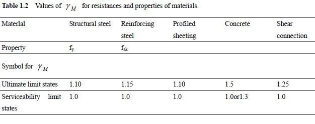
In Eurodode 4, the subscript M in M γ is replaced by a letter that indicates the material concerned, as shown in Table 1.2, which gives the values of M γ uses in this volume. A welded stud shear connector is treated like a single material, even though its resistance to shear, PR, is influenced by the properties of both steel and concrete.
1.3.2.3 Boxed values of γ γ andψ F M , ,
In the Eurocodes, numerical values given for these factors (and for certain other data) are enclosed in boxes. These indicate that the Members of CEN (the national standards organisations) are allowed to specify other values in their National Application Document. This may be necessary where characteristic actions are being taken from national codes, or where a country wishes to use a different margin of safety from that given by the boxes values.
The value of a γ , for structural steel, at ultimate limit states has been particularly controversial, and several countries (including the UK) are expected to adopt values lower than the 1.10 given in the Eurocodes and used in this volume.
1.3.2.4 Combinations of actions
The Eurocodes treat systematically a subject for with many empirical procedures have been used in the past. For ultimate limit states, the principles are:
* permanent actions are present in all combinations;
* each variable action is chosen in turn to be the leading action (i.e. to have its full design value), and is combined with lower combination values of other relevant variable actions;
* the design action effect is the most unfavourable of those calculated by this process.
The use of combination values allow for the lack of correlation between time-dependent variable actions.
As an example, it is assumed that a bending moment Md in a member is influenced by its own weight (G), by an imposed vertical load (Q1) and by wind loading (Q2). The fundamental combinations for verification for persistent design situations are:

In practice, it is usually obvious which combination will govern. For low-rise buildings, wind is rarely critical for floors, so expression (1.6), with imposed load leading, would be used; but for a long-span lightweight roof, expression (1.7) could govern, and both positive and negative wind pressures would be considered.
The combination for accidental design situations is given in Section 3.3.7.
For serviceability limit states, three combinations are defined. The most onerous of these, the rare combination, is recommended in Eurocode 4 for checking deformations of beams and columns. For the example given above, it is:

Assuming that 1 Q is the leading variable action, the others are:

The quasi-permanent combination is recommended in Eurocode 4 for checking widths of cracks in concrete. The frequent combination is not at present used in Eurocode 4; Part 1.1.
The values of the combination factors to be use in this volume, taken from draft Eurocode 1, are given in Table 1.3.

1.3.2.5 Simplified combinations of actions
Eurocode 4 allows the use of simplified combination for the design of building structures. For the example above, and assuming that 1 Q is more adverse than 2 Q , they are as follows:
* for ultimate limit states, the more adverse of
![]()

1.3.2.6 Comments on limit state design philosophy
Working stress or permissible stress design has been replaced by limit states design partly because limit states provide identifiable criteria for satisfactory performance. Stresses cannot be calculated with the same confidence as resistances of members, and high values may or may not be significant.
One apparent disadvantage of limit states design is that as limit states occur at various load levels, several sets of design calculations are needed, whereas with some older methods, one was sufficient. This is only partly true, for it has been found possible when drafting codes of practice to identify many situations in which design for, say, ultimate limit states will automatically ensure that certain types of serviceability will not occur; and vice versa. In Eurocode 4: Part 1.1 it has generally been possible to avoid specifying limiting stresses for serviceability limit states, by using the methods described in Sections 3.4.5, 3.7, 4.2.5 and 4.4.


