In this example, a typical composite T-beam is designed for the floor structure shown in Fig.3.1, using the materials specified in Section 3.2, and the floor design given in Section 3.4. Ultimate limit states are considered first. An a appropriate procedure hat minimizes trial and error is as follows:
(1) Choose the types and strengths of materials to be used.
(2) Ensure that the design brief is complete. For this example it is assumed that:
no special provision of holes for services is required;
the main source of vibration is pedestrian traffic on the floor, and occupants sensitivity to vibration is typical of hat found in office buildings; he specified fire resistance class is R60.
(3) Make policy decisions. For this design (for example);
steel member to be rolled universal beam (UB) section;
propped construction to be avoided, even if this involves pre-cambering the steel beam;
fire resistance to be provided by encasing the web, but not the bottom flange, in concrete.
(4) With guidance from typical span-to-depth ratios for composite beams, guess the overall depth ha of the steel section.
(5) Guess the weight of the beam, and hence estimate the design mid-span bending moment, MSd.
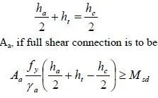
(6) Assume the lever arm to be (in the notation of Fig.3.2)

For partial shear connection, Aa should be increased.
(7) If full shear connection is to be used, check that the yield force in the steel, Aa ( f y/fγa ) y , is less than the compressive resistance of the concrete slab, (0.85 / ) eff e . If it is not, the plastic neutral axis will be in the steel-unusual in buildings-and Aa as found above will be too small.
(8) Knowing ha and Aa, select a rolled steel section. Check that its web can resist the design vertical shear at an end of the beam.
(9) Design the shear connection to provide the required bending resistance at midspan.
(10) Check deflections and vibration in service.
(11) Design for fire resistance.
3.11.1 Composite beam-flexure and vertical shear
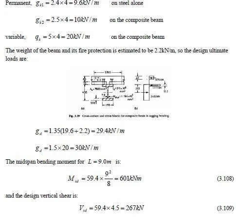
From Section 3.4, the uniform characteristic loads from a 4.0m width of floor are:

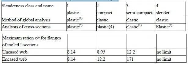
It had been assumed that the composite section will be in Class 1, so that the effects of unpropped
construction can be ignored at ultimate limit states.
Deflection of this beam in likely to influence its design, because of the use of steel with
f 355N /mm 2 y = (grade 50), lightweight-aggregate concrete, and unpropped construction.
The relatively low span-to-depth ratio of 16 is therefore chosen, giving an overall depth of
9000/16=562mm. The slab is 150mm thick (FIG.3.9), so for the steel beam, h mm a = 412 .
From equation (3.107) the required area of steel is

