A cable is a linear structural member, like a bar of a truss. The cross-sectional dimensions of a cable relative to its length, however, are so small that it cannot withstand bending or compression. Consequently, under loads at an angle to its longitudinal axis, a cable sags and assumes a shape that enables it to develop tensile stresses that resist the loads.
Structural efficiency results from two cable characteristics: (1) uniformity of tensile stresses over the cable cross section, and (2) usually, small variation of tension along the longitudinal axis. Hence, it is economical to use materials with very high tensile strength for cables.
Cables sometimes are used in building construction as an alternative to such tension members as hangers, ties, or tension chords of trusses. For example, cables are used in a form of long-span cantilever-truss construction in which a horizontal roof girder is supported at one end by a column and near the other end by a cable that extends diagonally upward to the top of a vertical mast above the column support (cable-stayed-girder construction, Fig. 5.100). Cable stress an be computed for this case from the laws of equilibrium.
Cables also may be used in building construction instead of girders, trusses, or membranes to support roofs, For the purpose, cables may be arranged in numerous ways. It is consequently impractical to treat in detail in this book any but the simplest types of such applications of cables. Instead, general procedures for analyzing cable-supported structures are presented in the following.
Simple Cables
An ideal cable has o resistance to bending. Thus, in analysis of a cable in equilibrium, not only is the sum of the moments about any point equal to zero but so is the bending moment at any point. Consequently, the equilibrium shape of the cable corresponds to the funicular, or bending-moment, diagram for the loading (Fig. 5.101a). As a result, the tensile force at any point of the cable is tangent there to the cable curve.
The point of maximum sag of a cable coincides with the point of zero shear.
(Sag in this case should be measured parallel to the direction of the shear forces.)
Stresses in a cable are a function of the deformed shape. Equations needed for analysis, therefore, usually are nonlinear. Also, in general, stresses and deformations cannot be obtained accurately by superimposition of loads. A common procedure in analysis is to obtain a solution in steps by using linear equations to approximate the nonlinear ones and by starting with the initial geometry to obtain better estimates of the final geometry.
For convenience in analysis, the cable tension, directed along the cable curve, usually is resolved into two components. Often, it is advantageous to resolve the tension T into a horizontal component H and a vertical component V (Fig. 5.100b).
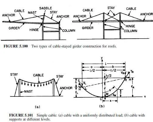
Under vertical loading then, the horizontal component is constant along the cable.
Maximum tension occurs at the support. V is zero at the point of maximum sag.
For a general, distributed vertical load q, the cable must satisfy the second-order linear differential equation
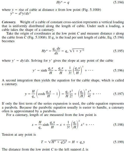
The distance from the low point C to the left support L is

Cable Systems
Analysis of simple cables is described in Art. 5.16.1. Cables, however, may be assembled into many types of systems. One important reason for such systems is that roofs to be supported are two- or three-dimensional. Consequently, threedimensional cable arrangements often are advantageous. Another important reason is that cable systems can be designed to offer much higher resistance to vibrations than simple cables do.
Like simple cables, cable systems behave nonlinearly. Thus, accurate analysis is difficult, tedious, and time-consuming. As a result, many designers use approximate methods that appear to have successfully withstood the test of time. Because of the numerous types of systems and the complexity of analysis, only general procedures will be outlined in this article.
Cable systems may be stiffened or unstiffened. Stiffened systems, usually used for suspension bridges are rarely used in buildings. This article will deal only with unstiffened systems, that is, systems where loads are carried to supports only by cables.
Often, unstiffened systems may be classified as a network or as a cable truss, or double-layered plane system.
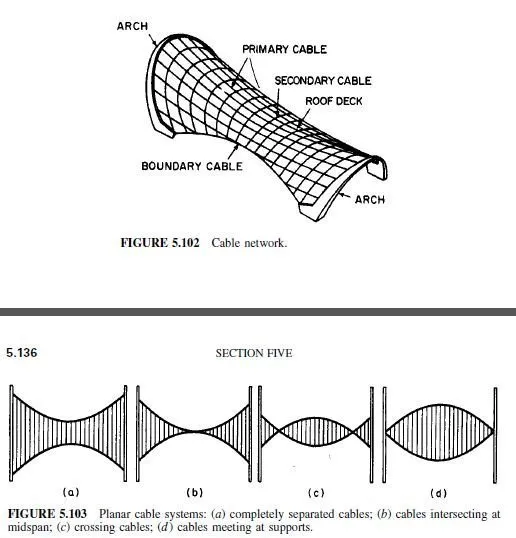
Networks consist of two or three sets of cables intersecting at an angle (Fig. 5.102). The cables are fastened together at their intersections.
Cable trusses consist of pairs of cables, generally in a vertical plane. One cable of each pair is concave downward, the other concave upward (Fig. 5.103).
Cable Trusses. Both cables of a cable truss are initially tensioned, or prestressed, to a predetermined shape, usually parabolic. The prestress is made large enough that any compression that may be induced in a cable by loads only reduces the tension in the cable; thus, compressive stresses cannot occur. The relative vertical position of the cables is maintained by verticals, or spreaders, or by diagonals.
Diagonals in the truss plane do not appear to increase significantly the stiffness of a cable truss.
Figure 5.103 shows four different arrangements of the cables, with spreaders, in a cable truss. The intersecting types (Fig. 5.103b and c) usually are stiffer than the others, for given size cables and given sag and rise.
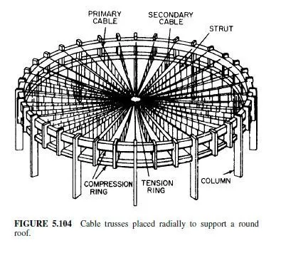
For supporting roofs, cable trusses often are placed radially at regular intervals (Fig. 5.104). Around the perimeter of the roof, the horizontal component of the tension usually is resisted by a circular or elliptical compression ring. To avoid a joint with a jumble of cables at the center, the cables usually are also connected to a tension ring circumscribing the center.
Properly prestressed, such double-layer cable systems offer high resistance to vibrations. Wind or other dynamic forces difficult or impossible to anticipate may cause resonance to occur in a single cable, unless damping is provided. The probability of resonance occurring may be reduced by increasing the dead load on a single cable. But this is not economical, because the size of cable and supports usually must be increased as well. Besides, the tactic may not succeed, because future loads may be outside the design range. Damping, however, may be achieved economically with interconnected cables under different tensions, for example, with cable trusses or networks.
The cable that is concave downward (Fig. 5.103) usually is considered the loadcarrying cable. If the prestress in that cable exceeds that in the other cable, the
natural frequencies of vibration of both cables will always differ for any value of live load. To avoid resonance, the difference between the frequencies of the cables should increase with increase in load. Thus, the two cables will tend to assume different shapes under specific dynamic loads. As a consequence, the resulting flow of energy from one cable to the other will dampen the vibrations of both cables.
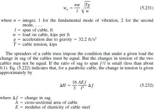
Natural frequency, cycles per second, of each cable may be estimated from
Double cables interconnected with struts may be analyzed as discrete or continuous systems. For a discrete system, the spreaders are treated as individual members.
For a continuous system, the spreaders are replaced by a continuous diaphragm that ensures that the changes in sag and rise of cables remain equal under changes in load. Similarly, for analysis of a cable network, the cables, when treated as a continuous system, may be replaced by a continuous membrane.
