When some slip, although very small, may occur between connected parts, the fasteners are assumed to function in shear. The presence of paint on contact surfaces is therefore of no consequence. Fasteners may be A307 bolts or high-strength bolts or any other similar fastener not dependent on development of friction on the contact surfaces.
Single shear occurs when opposing forces act on a fastener as shown in Fig. 7.39a, tending to slide on their contact surfaces. The body of the fastener resists this tendency; a state of shear then exists over the cross-sectional area of the fastener.
Double-shear takes place whenever three or more plates act on a fastener as illustrated in Fig. 7.40b. There are two or more parallel shearing surfaces (one on each side of the middle plate in Fig. 7.40b). Accordingly, the shear strength of the fastener is measured by its ability to resist two or more single shears.
Bearing on Base Metal. This is a factor to consider; but calculation of bearing stresses in most joints is useful only as an index of efficiency of the net section of tension members.


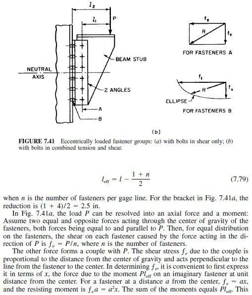
Eccentric Loading. Stress distribution is not always as simple as for the joint in Fig. 7.40a where the fastener is directly in the line of significant. Sometimes, the load is applied eccentrically, as shown in Fig. 7.41. For such connections, tests show that use of actual eccentricity to compute the maximum force on the extreme fastener is unduly conservative because of plastic behavior and clamping force generated by the fastener. Hence, it is permissible to reduce the actual eccentricity to a more realistic effective eccentricity.
For fasteners equally spaced on a single gage line, the effective eccentricity in inches is given by

Tension and Shear. For fastener group B in Fig. 7.41b, use actual eccentricity l2 since these fasteners are subjected to combined tension and shear. Here too, the load P can be resolved into an axial shear force through the fasteners and a couple.
Then, the stress on each fastener caused by the axial shear is P/n, where n is the number of fasteners. The tensile forces on the fasteners vary with distance from the center of rotation of the fastener group.
A simple method, erring on the safe side, for computing the resistance moment of group B fasteners assumes that the center of rotation coincides with the neutral axis of the group. It also assumes that the total bearing pressure below the neutral axis equals the sum of the tensile forces on the fasteners above the axis. Then, with these assumptions, the tensile force on the fastener farthest from the neutral axis is


