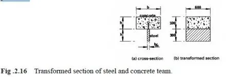
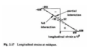
Full-interaction and no-interaction elastic analyses are given in Section 2.2 for a composite beam made from two elements of equal size and stiffness. Its cross-section (Fig.2.2(b))can be considered as the transformed section for the steel and concrete beam in Fig .2.16 Partial-interaction analysis of this beam (Appendix A)illustrates well the effect of connector flexibility on interface slip and hence onstresses and deflections, even though the cross-section is not that would be used in practice.  The numerical values, chosen to be typical of a composite beam, are given in section A.2.Substituon in (2.27)gives the relation between sand x for a beam of depth 0.6m and span 10m as. 10^4 s =1.05x − 0.007 sinh(1.36x). The maximum slip occurs at the ends of the span, where x= ± 5.m From equation(2.28) it is ± 0.45mm. The results obtained in Sections 22.1 and 22.2are also applicable to this beam. From equation (2.6) the maximum slip if there were no shear connection would be ± 8.1mm.Thus the shear connectors reduce end slip substantially, but do not eliminate it .The variations of slip strain and slip along the span for no interaction and parial interaction are shown in Fig 2.3 The connector modulus k was taken as 150 kN / mm(Appendix A).The maximum load per connetor is k timews the maximum slip ,so the maximum slip so the partial-interaction theory gives this load as 67 kN, which is sufficiently far below the ultimate strength of 100 kN per connector for the assumption of a linear Load slip relationship to be reasonable. Longitudinal strains at midspan given by full-interaction and partial-interaction and partial interaction theories are shown in Fig 2.17 The increase in extreme-fibre strain due to slip , 28 ×10−6 , is much less stress in the concrete is increasede,104×10−6 .The maximum compressive stress in the concrete is increased by slip form 12.2 to 12.8 N/mm2,a change of 5%.This higher stress is 43% of the cube strength, so the assumption of elastic behaviour is reasonable

The ratio of the partial-interaction curaturv to the full-interaction curvature is 690/610, or 1.13, Integration due to slip, is also about 13%. The effects of slip on deflection are found in pratice to be less than is implied by this example, because here a rather low value of conncctor modulus has been used ,and the effect of bond has been neglected.
The longitudinal compressive force in the concrete at midspan is proportional to the mean compressive strain. From Fig 2.17 , this is 305×10-6for full interaction and 293×10-6for partial interaction ,a reduction of 4%

The influence of slip on the flexural behaviour of the member may be summarized as follows ,The bending moment at midspan ,WL^2/8. Can be considered to be the sum of a concrete moment Mc, a steel moment Ms and a composite moment Fdc(Fig.A.1):
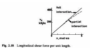
In the full-interaction analysis c Fd contributes 75%.of the total moment ,and c M and a M 12.5% each. The Parial-interaction analysis shows that slip reduces the contribution from Fdc to 72% of the total, so that the contributions from Mc and Ma rise to 14%,corresponding to an increase in curvature of (14-12.5) ,or about 13%. The interface shear force per unit length Vx is??given by equation (2.12)for full interaction and by equations (A.1)and (2.28)for partial inter action The expressions for Vx over a half span are plotted in Fig 2.18,and show that in the elastic range ,the distribution of loading on the connectors is similar to that given by full-interaction theory. The reasons for using uniform rather than triangular spacing of connectors are discussed in section 3.6.