If map of an area is available its area can be found by the following methods:
(i) Approximate methods (ii) Using planimeter.
Approximate Methods
The following three approximate methods are available for calculating area from the map:
(a) Give and take method (b) Subdivisions into squares
(c) Subdivisions into rectangles.
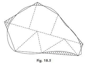
(a) Give and take method: In this method irregular boundary is approximated with straight
lines such that area taken in is equal to the area given out. Accuracy depends upon the judging capacity of the engineer. Then the area with straight edges is divided into a set of simple figures, like triangles and trapezoids and the area of map is found using standard expressions.
Figure 18.5 shows such a scheme.
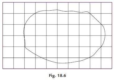
(b) Subdivisions into squares: Similar to a graph sheet, squares are marked on a transparent tracing sheet, each square representing a known area. Full squares are counted. Fractional squares are counted by give and take approximation. Then the number of squares multiplied by area of each square gives the area of the map Fig. 18.6 shows such a scheme. Finer the mesh better is the accuracy.
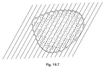
(c) Subdivisions into rectangles: In this method, a set of parallel lines are drawn at equal spacing on a transparent paper. Then that sheet is placed over the map and slightly rotated till two parallel lines touch the edges of the tap. Then equalising perpendiculars are drawn between the consecutive parallel line. Thus given area is converted to equivalent set of rectangles and then area is calculated (Ref. Fig. 18.7).
Computing Area Using Planimeter
Planimeter is a mechanical instrument used for measuring area of plan. The commonly used planimeter is known as Amsler planimeter (Fig. 18.8). Its construction and uses are explained in this article.

The essential parts of a planimeter are:
1. Anchor: It is a heavy block with a fine anchor pin at its base. It is used to anchor the instrument at a desired point on the plan.
2. Anchor arm: It is a bar with one end attached to anchor block and the other connected to an integrating unit. Its arm length is generally fixed but some planimeters are provided with variable arms length also.
3. Tracing arm: It is a bar carrying a tracer point at one end connected to the integrating unit at the other end. The anchor arm and tracer arms are connected by a hinge. The length of this arm can be varied by means of fixed screw and slow motion screw.
4. Tracing point: This is a needle point connected to the end of tracer arm, which is to be
moved over the out line of the area to be measured.
5. Integrating unit: It consists of a hard steel roller and a disc. The axis of roller coincides with the axis of tracer arm hence it rolls only at right angles to the tracer arm. The roller carries a concentric drum which has 100 divisions and is provided with a vernier to read tenth of roller division. A suitable gear system moves a pointer on disc by one division for every one revolution of the roller. Since the disc is provided with 10 such equal divisions, the reading on the integrating unit has four digits:
(i) Unit read on the disc
(ii) Tenth and hundredth of a unit read on the roller
(iii) Thousandth read on the vernier.
Thus if reading on disc is 2, reading on roller is 42 and vernier reads 6, then the total reading F = 2.426
Method of Using Planimeter
To find the area of a plan, anchor point may be placed either outside the plan or inside the plan. It is placed outside the plan, if the plan area is small. Then on the boundary of the plan a point is marked and tracer is set on it. The planimeter reading is taken. After this tracer is carefully moved over the outline of the plan in clockwise direction till the first point is reached. Then the reading is noted. Now the area of the plan may be found as
Area = M (F I + 10 N + C)
where M = A multiplying constant
F = Final reading
I = Initial reading.
N = The number of completed revolutions of disc. Plus sign to be used if the zero mark of the dial passes index mark in clockwise direction and minus sign if it passes in anticlockwise direction.
C = Constant of the instrument, which when multiplied with M, gives the area of zero circle.
The constant C is added only when the anchor point is inside the area.
Multiplying constant M is equal to the area of the plan (map) per revolution of the roller i.e., area
corresponding to one division of disc.
Multiplying constant M and C are normally written on the planimeter. The user can verify these values by
(i) Measuring a known area (like that of a rectangle) keeping anchor point outside the area
(ii) Again measuring a known area by keeping anchor point inside a known area.
The method is explained with example.
The proof of equation 18.7 is considered as beyond the scope of this book. Interested readers can see the book on surveying and levelling.
