The required domestic-water pipe sizes should be determined by application of the principles of hydraulics. While economy dictates use of the smallest sizes of pipe permitted by building-code requirements, other factors often make larger sizes advisable.
These factors include:
1. Pressure at the water-supply source, usually the public main, psi
2. Pressure required at the outlets of each fixture, psi
3. Loss of pressure because of height of outlets above the source, pressure loss due
to friction caused by the flow of water through water meters and backflow preventers, and friction from water flow in the piping
4. Limitations on velocity of water flow, ft / s, to prevent noise and erosion
5. Additional capacity for future expansion (normally 10% minimum)
Method for Determining Pipe Sizes
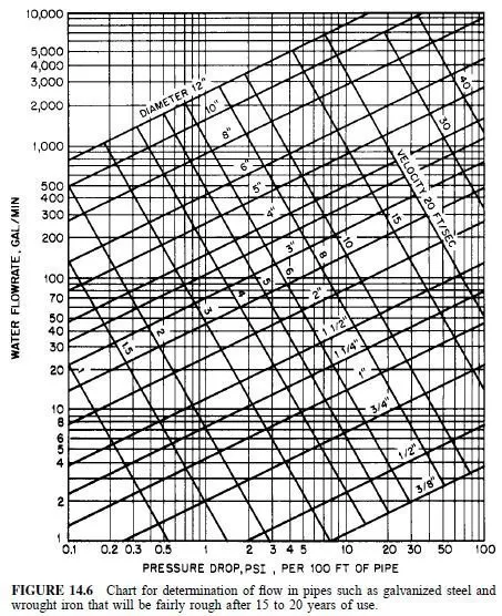
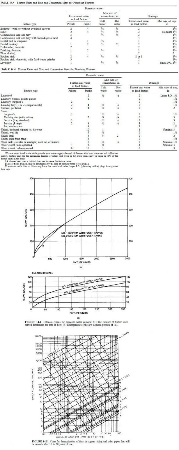
1. Sketch all the proposed risers, horizontal mains, and branch lines, indicating the number and the type of fixtures served, together with the required flow 2. Compute the demand weights of the fixtures, in fixture units, using Table 14.4 3. From Fig. 14.4 and the total number of fixture units, determine the water demand, gal /mm 4. Compute the equivalent length of pipe for each stack in the system, starting from the street main 5. Obtain by test or from the water company the average minimum pressure in the street main. Determine the minimum pressure needed for the highest fixture in the system 6. Compute the pressure loss in the piping with the use of the equivalent length found in item 4 7. Choose the pipe sizes from a chart like that in Fig. 14.5 or 14.6, or from the charts given in the plumbing code being used
Effects of Pressure
Rate of flow, ft^3 / s, in a pipe is determined by

In general, V should be kept to 8 ft / s or less to prevent noise and reduce erosion at valve seats. Hence, pipe area should be at least the flow rate Q divided by 8.

Mains may be allowed to have a velocity of 10 ft / s, but lower velocities are preferred.
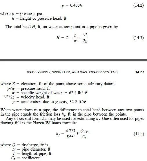
The minimum pressures at plumbing fixtures generally required by building codes are listed in Table 14.1. These pressures are those that remain when the pressure drop due to height of outlet above the water source and the pressure lost by friction in pipes are deducted from the pressure at the water source. The pressure loss due to height can be computed from

The value of C1 depends on the roughness of the pipe, which, in turn, depends on pipe material and age. A new pipe has a larger C1 than an older one of the same size and material. Hence, when pipe sizes are being determined for a new installation, a future value of C1 should be assumed to ensure adequate flows in the future. Design aids, such as charts (Figs. 14.5 and 14.6) or nomograms, may be used to evaluate Eq. (14.4), but if such computations are made frequently, a computer solution is preferable.
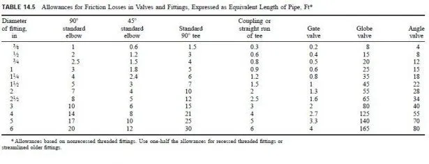
In addition to friction loss in pipes, there are also friction losses in meters, valves, and fittings. These pressure drops can be expressed for convenience as equivalent lengths of pipe of a specific diameter. Table 14.5 indicates typical allowances for friction loss for several sizes and types of fittings and valves.
The pressure reduction caused by pipe friction depends, for a given length of pipe and rate of flow, on pipe diameter. Hence, a pipe size can be selected to create a pressure drop in the pipe to provide the required pressure at a plumbing fixture, when the pressure at the water source is known. If the pipe diameter is too large, the friction loss will be too small and the pressure at the fixture will be high. If the pipe size is too small, the friction loss will be too large and the pressure at the fixture will be too small.
Minimum Pipe Sizes
The minimum sizes for fixture-supply pipes are given for cold water and hot water in Table 14.4.
Sizes of pipes for small buildings, such as single-family houses, can usually be determined from the experience of the designer and applicable building-code requirements, without extensive calculations. For short branches to individual fixtures, for example, the minimum pipe diameters listed in Table 14.4 generally will be satisfactory. Usually also, the following diameters can be used for the mains supplying water to the fixture branches:
1â„2 in for mains with up to three 3â„4-in branches
3â„4 in for mains with up to three 1â„2-in or five 3â„8-in branches 1 in for mains with up to three 3â„4-in or eight 1â„2-in or fifteen 1â„8-in branches The adequacy of these sizes, however, depends on the pressure available at the water source and the probability of simultaneous use of the plumbing fixtures.

