5.1 General
Distances may be measured by four methods: direct, optical, electromagnetic or GPS. The method used for any particular job depends upon the nature of the ground, the range, the accuracy, the number of distances to be measured, the time available, and the cost and the availability of the equipment. For all but the smallest or largest tasks, electromagnetic distance measurement (EDM) is the simplest choice for terrestrial measurement. GPS measurements provide inter-point distances over any distance and without the need for inter-visibility, but the procedure is somewhat more complex. Before making any measurement, it is wise to obtain an estimate of its value by an approximate method, to reduce the possibility of gross errors. At least three methods are available for this: 1 Pacing is used for rough measurements and to check accurate measurements against gross errors. Test your natural pace over a measured distance, rather than trying to pace metres. The accuracy on smooth ground is about 1 part in 50. 2 A perambulator is a wheel fitted with a revolution counter and is wheeled along the line to be measured. It is more accurate than pacing and is frequently used in measurement for costing of highway repairs. 3 If a suitable map is available, scaling from it will give a close approximation.
5.2 Tape measurements
Tapes are now mainly used only for the quick measurements of short distances (horizontal or vertical). However, they used to be the most accurate method of measuring all distances, so their use was developed to a fine art by surveyors in the first part of the twentieth century. Tape measurements are subject to the following sources of error:
1 inaccuracy in the length of the tape;
2 variations in the length of the tape due to changes in temperature;
3 variations in the length of the tape due to changes in tension;
4 slope (since it is usually the horizontal component of the length that is required);
5 sag on any unsupported spans;
6 errors at the junction of tape lengths.
For further details of precision taping, see Bannister et al. (1998).
Surface taping
Fabric tapes made of linen or preferably of fibreglass are used for low accuracy or detail work. Steel bands or tapes are more accurate but are easily damaged if kinked or trodden on. On smooth ground, an accuracy of about 1/2,000 is attainable. For the highest accuracy:
1 calibrate the tape against a known distance, at the same temperature and tension as will
be used on the job;
2 avoid large changes of temperature by working early, late or on a cloudy day;
3 use a steady pull, ideally by means of a spring balance;
4 correct for slope; if there are marked changes of gradient, measure the slope and note
the length of each section;
5 use the longest tape possible, if the distance is greater than one tape length;
6 take the mean of two measurements in opposite directions.
5.3 Optical methods (tachymetry)
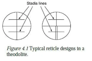
The stadia hairs (Figure 4.1) on the reticle of a theodolite or level subtend a particular angle α, usually 1/100 radian. Thus, if a distant vertical staff is viewed horizontally by means of a theodolite, the distance D from the instrument to the staff is given by s/α (i.e. usually 100s) where s is the length of the staff between the two stadia hairs. Either an ordinary levelling staff or a specially made tachymetry staff may be used. This method of determining distance is perfectly straightforward when the line of sight is horizontal, and modern digital levels also use this principle to measure the distance to their (bar-coded) levelling staffs. However, it becomes more complex if the line of sight of a theodolite needs to be inclined by some angle to the horizontal in order to observe the staff. It is not practicable to hold the distant staff perpendicular to such a line of sight; instead, it is still held vertical by means of a spirit level, and the two readings (plus the vertical angle of the theodolite) can be used to obtain both the horizontal distance to the staff and the height difference between the instrument and the base of the staff. The calculations for this form of tachymetry are tiresome, and the technique is now largely obsolete.1 In any case, the accuracy of vertical staff tachymetry is always limited by the fact that lines of sight defined by the two stadia hairs are differently affected by atmospheric refraction. For distances up to about 50 m, a form of horizontal staff tachymetry, known as subtense, is still sometimes used. A special staff called a subtense bar, usually 2 or 3 m long, is mounted horizontally and at right angles to the direction of view. The horizontal angle subtended at the instrument is then measured, and the horizontal distance can be deduced by simple trigonometry.
Surface taping
Fabric tapes made of linen or preferably of fibreglass are used for low accuracy or detail
work. Steel bands or tapes are more accurate but are easily damaged if kinked or trodden
on. On smooth ground, an accuracy of about 1/2,000 is attainable. For the highest
accuracy:
1 calibrate the tape against a known distance, at the same temperature and tension as will
be used on the job;
2 avoid large changes of temperature by working early, late or on a cloudy day;
3 use a steady pull, ideally by means of a spring balance;
4 correct for slope; if there are marked changes of gradient, measure the slope and note
the length of each section;
5 use the longest tape possible, if the distance is greater than one tape length;
6 take the mean of two measurements in opposite directions.
5.3 Optical methods (tachymetry)
The stadia hairs (Figure 4.1) on the reticle of a theodolite or level subtend a particular angle α, usually 1/100 radian. Thus, if a distant vertical staff is viewed horizontally by means of a theodolite, the distance D from the instrument to the staff is given by s/α (i.e. usually 100s) where s is the length of the staff between the two stadia hairs. Either an ordinary levelling staff or a specially made tachymetry staff may be used. This method of determining distance is perfectly straightforward when the line of sight is horizontal, and modern digital levels also use this principle to measure the distance to their (bar-coded) levelling staffs. However, it becomes more complex if the line of sight of a theodolite needs to be inclined by some angle to the horizontal in order to observe the staff. It is not practicable to hold the distant staff perpendicular to such a line of sight; instead, it is still held vertical by means of a spirit level, and the two readings (plus the vertical angle of the theodolite) can be used to obtain both the horizontal distance to the staff and the height difference between the instrument and the base of the staff. The calculations for this form of tachymetry are tiresome, and the technique is now largely obsolete.1 In any case, the accuracy of vertical staff tachymetry is always limited by the fact that lines of sight defined by the two stadia hairs are differently affected by atmospheric refraction. For distances up to about 50 m, a form of horizontal staff tachymetry, known as subtense, is still sometimes used. A special staff called a subtense bar, usually 2 or 3 m long, is mounted horizontally and at right angles to the direction of view. The horizontal angle subtended at the instrument is then measured, and the horizontal distance can be deduced by simple trigonometry.
5.4 Electromagnetic methods (EDM)
The principle of the method depends on measuring the transit time of an electromagnetic wave which is transmitted along the line and reflected back to the transmitter. Some devices transmit a pulsed laser beam and simply measure the time taken for the pulse to be reflected this can be done without the need for a special reflector at the far end of the line and is known as a reflectorless system. Others use a carrier wave modulated at a known frequency and measure the phase change of the reflected modulation to calculate the distance (see Figure 5.1). Errors can arise from difficulties in knowing the exact point of measurement within the instrument (a matter of a few millimetres), from inaccuracies in measurement (usually fewer than 10 parts per million) and from variations in atmospheric temperature and pressure along the path of the wave (up to about 20 parts per million, if no correction is made).
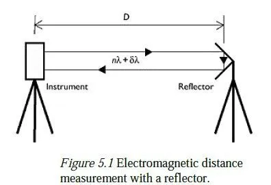
The reflectors (for those instruments which require them) take the form of corner cubes with precisely ground faces, so that the radiation is reflected back along the exact path it came along. It is important to use only the correct type of reflector with a given instrument, since each type has a different distance constant, depending on the path length of the optics and the density of the glass. Neglect of this factor will lead to a systematic error in all measurements. Most modulating EDM devices now use infrared or a visible laser (wavelength a few microns) as the carrier wave, modulated at around 1 GHz to give a modulation wavelength of about 30 cm. Their range can be up to 30 km. Some earlier instruments used microwaves (wavelength a few centimetres) as a carrier and were capable of measuring up to 100 km, provided that the end stations were inter-visible. (Measurements of this length would now be done by GPS.) The total distance travelled by the modulated wave, 2D, will be equal to a number of whole wavelengths nλ plus a fraction of a wavelength λδ (see Figure 5.1). δ is relatively easy to determine by comparing the phase of the reflected wave with that of the transmitted wave. Some possible methods are:
1 to use a phase discriminator circuit to compare phases directly;
2 to shift the phase of the reflected signal by a known amount until it gives a null with the
reference signal;
3 to use a digital count of time signals between the reference null and the reflected null,
then multiply by the modulation frequency to find the phase difference.
The value of n can be found by increasing the modulation frequency by a small fraction and measuring the change in δ. Typically, the modulation frequency is increased by 1 per cent; the resulting fractional change in δ is then multiplied by 100 and rounded down to the nearest integer to give the value of n. The change in δ is measured by changing to the new frequency and subtracting the new value of δ from the old value, adding one whole cycle in cases where δ appears to have decreased. However, this method only works properly when n is less than 100; any multiples of 100 would pass undetected. Such multiples can, however, be counted by altering the frequency by 0.01 per cent (1 per cent of 1 per cent) and again measuring the fractional change in δ. Long-range machines may thus need to make several changes of modulation frequency to compute the distance properly.
Use of EDM
For short-range work, hand-held laser devices can be used to measure distances with an accuracy of around 3 mm, without the need for a reflecting target at the far end of the ray. EDM systems mounted on tripods are used for high-accuracy (5 parts per million) measurements of distances between, say, 10 m and a kilometre. Longer distances are now generally measured using GPS. Although the instruments required for GPS are more expensive, they are more accurate (2 parts per million) and they save time, especially in rough country and in conditions where the line being measured is obstructed (e.g. by buildings) or subject to interference by traffic. The basic measurement made by an EDM device is a slope distance between the instrument and the target, uncorrected for atmospheric conditions. On most instruments, it is possible to correct for atmospheric conditions while in the field. Temperature and pressure are measured near the instrument (and for accurate work, near the target), and a nomogram or slide rule is provided to convert these readings into a parts-per-million correction, which is then entered into the instrument. To guard against undetected errors, it is wise also to record the temperature, pressure and uncorrected distance, so that the field correction can be checked back in the office. Some EDMs do not always show the whole of the distance that they are measuring; for instance, the display might show 2,345.678 when the distance is actually 12,345.678. A 10 km error should not easily pass unnoticed, but a useful field check is to record the readings obtained with the atmospheric correction set first to +50 ppm and then to −50 ppm. The difference between the two readings, when multiplied by 104, gives the approximate distance, and any overflow in the display will then be detected quite easily. In addition to slope distance, most EDMs are also able to calculate the horizontal and vertical distances between the instrument and the target. In the case of horizontal distance, this has the advantage that the heights of the instrument and the target above their stations do not need to be measured, since the horizontal distance between the instrument and the target will also be the horizontal distance between their respective stations. (For the other distance measurements to be useful, it is of course vital that these measurements are recorded.) To make a calculation of horizontal or vertical distance, the microprocessor inside the EDM must know the vertical angle between the instrument and the target. This means that the instrument must be carefully aimed at the target; it is not sufficient simply to sight it well enough for the radiated signal to be returned. Additionally, on some detachable instruments, a calibration must be set so that the correct vertical angle is displayed. The relevant angle is obtained from the theodolite to which the instrument is attached, remembering to centre the alidade bubble if necessary. For precise or long-distance work, however, these calculated distances must be treated with caution. A fully accurate horizontal distance calculation involves knowing the height of the instrument above sea level, and both calculations have to make some assumption about how light curves in the atmosphere, which may not be valid at the time of the measurement. Chapter 11 discusses both of these issues in detail.