Since seismic loading is an inertial loading, the forces are dependent on the dynamic characteristics of the acceleration record and the structure. Seismic design codes use a response spectrum as shown in Fig. 9.7 to model these dynamic characteristics. These forces are usually reduced in accordance with the ductility of the structure. This reduction is accomplished by the R factor in the static-force method, and the reduction may be quite large (Art. 9.5). The designer must ensure that the structure is capable of developing the required ductility, as it is well-known that the available ductility varies with different structural systems.
Therefore, the structural engineer must ensure that the structural system selected for a given application is capable of achieving the ductility required for the R value used in the design. The engineer also must complete the details of the design of members and connections so that the structure lives up to these expectations.
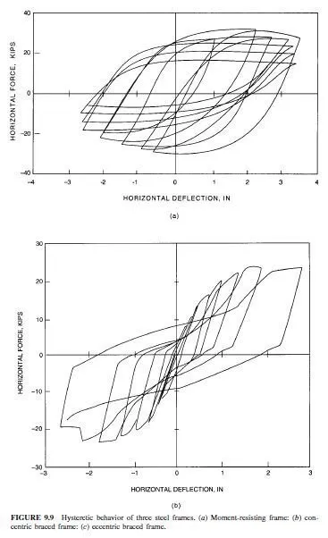
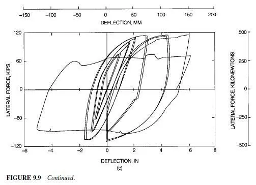
Evaluation of Ductility. Two major factors may affect evaluation of the ductility of structural systems. First, the ductility is often measured by the hysteretic behavior of the critical components. The hysteretic behavior is usually examined by observing the cyclic forcedeflection (or moment-rotation) behavior as shown in Fig. 9.9. The slope of the curves represents the stiffness of the structure or component. The enclosed areas represent the energy that is dissipated, and this can be large, because of the repeated cycles of vibration. These enclosed areas are sometimes full and fat (Fig. 9.9a), or they may be pinched or distorted (Fig. 9.9b). The hysteretic curves also show the inelastic deformation that can be tolerated at various resistance levels. Structural framing with curves enclosing a large area representing large dissipated energy, and structural framing which can tolerate large inelastic deformations without excessive loss in resistance, are regarded as superior systems for resisting seismic loading. As a result, these systems are commonly designed with larger R values and smaller seismic loads.
Special steel moment-resisting frames and eccentric braced frames, defined in Art. 9.4, are capable of developing large plastic deformations and large hysteretic areas. As a result, they are designed for larger values of R, thus smaller seismic forces and greater inelastic deformation. This hysteretic behavior is important, since it dampens the inelastic response and improves the seismic performance of the structure without requiring excessive strength or deformation in the structure. This is illustrated in Fig. 9.8, which shows the inelastic
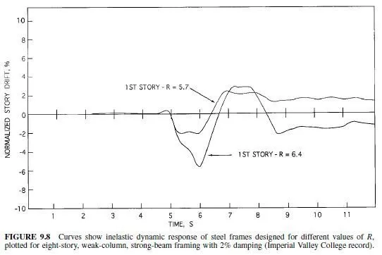
dynamic response of two steel moment-resisting frames, which had identical mass, stiffness and seismic excitation (1979 Imperial Valley College), but different seismic resistance. The story drift and inelastic deformation cycles are larger for the structure with the smaller resistance. This shows that structures with smaller design force (larger R) require the structure to have the ability to maintain its integrity through larger inelastic deformations than if a larger design force (smaller R) were employed.
While some steel structures are very ductile, not all structures have this great ductility.
Fracture of the connections has a very detrimental effect on the structural performance, since it may cause a significant loss in both resistance and deformational capacity. Local and global buckling may also change the hysteretic behavior from that of Fig. 9.9a to Fig. 9.9b. The combined effects of these potential problems means that the structural engineer must pay particular attention to the design details in the seismic design of buildings, since those details are essential to ensuring good seismic performance.
Effects of Inelastic Deformations. The distribution of inelastic deformation is a second factor that can effect the inelastic seismic performance of a structural system. Some structural systems concentrate the inelastic deformation (ductility demand) into a small portion of the structure. This can dramatically increase the ductility demand for that portion of the structure.
This concentration of damage is sometimes related to factors that cause pinched hysteretic behavior, since buckling may change the stiffness distribution as well as affect the energy dissipation.
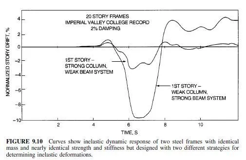
Ductility demand, however, can also be related to other factors. Figure 9.10 shows the computed inelastic response of two steel moment-resisting frames that have identical mass and nearly identical strength and stiffness and are subject to the same acceleration record as that in Fig. 9.8. The frames differ, however, in that one is designed to yield in the beams while the other is designed to yield in the columns. This difference in design concept results in a significant difference in seismic response and ductility demand. Design codes attempt to assure greater ductility from structures designed for smaller seismic forces, but attaining this objective is complicated by the fact that ductility and ductility demand are not fully understood.
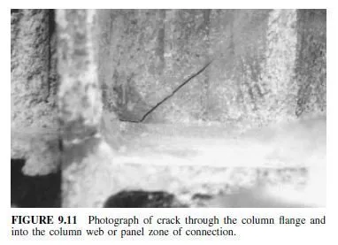
Steel moment-resisting frames have historically been regarded as the most ductile structural system for seismic design, but a number of special steel moment frames sustained damage during the January 17, 1994, Northridge earthquake. In these buildings, cracks were initiated near the flange weld. Some of the cracks penetrated into the column and panel zone of the beam-column connections as illustrated in the photo of Fig. 9.11, but others penetrated into the beam flange or the flange welds and the heat-affected zones of these welds. None of these buildings collapsed and there was no loss of life, but the economic loss was considerable.
This unexpected damage has caused a new evaluation of the design of moment frame connections through the SAC Steel Project. SAC is a joint venture of SEAOC, ATC (Applied Technology Council), and CUREE (California Universities for Research in Earthquake Engineering), and the joint venture is funded by FEMA. This work is still in progress, but it is clearly leading structural engineers in new directions in the design of special steel moment frame buildings. The work shows that great ductility is possible, but it also shows that the engineer must exercise great care in the selection and design of members and connections.
The requirements that are evolving for special moment frames are briefly summarized in Art. 9.7.1.
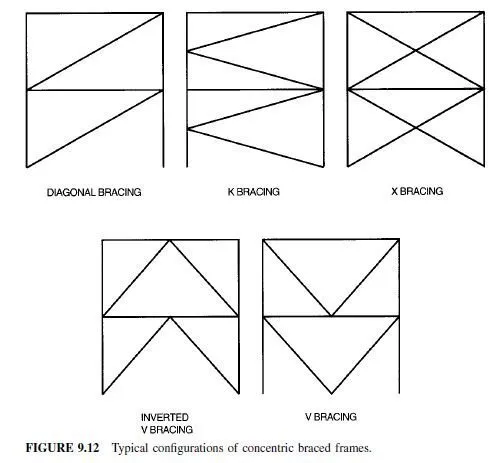
Concentric braced frames, defined in Art. 9.4, economically provide much larger strength and stiffness than moment-resisting frames with the same amount of steel. There are a wide range of bracing configurations, and considerable variations in structural performance may result from these different configurations. Figure 9.12 shows some concentric bracing configurations. The braces, which provide the bulk of the stiffness in concentrically braced frames, attract very large compressive and tensile forces during an earthquake. As a result, compressive buckling of the braces often dominates the behavior of these frames. The pinched cyclic force-deflection behavior shown in Fig. 9.9b commonly results, and failure of braces may be quite dramatic. Therefore, concentrically braced frames are regarded as stiffer, stronger but less ductile than steel moment-resisting frames. In recent years, research has shown that concentrically braced frames can sustain relatively large inelastic deformation without failure if greater care is used in the design and selection of the braces and the brace connections. Concentrically braced frames, which are designed to these higher ductility standards, can be designed for smaller seismic design forces and are called special concentrically braced frames. Different design provisions are required for ordinary concentrically braced frames and special concentrically braced frames. These are summarized in Art. 9.7.2.
Eccentric braced frames, defined in Art. 9.4, can combine the strength and stiffness of concentrically braced frames with the good ductility of moment-resisting frames. Eccentric braced frames incorporate a deliberately controlled eccentricity in the brace connections (Fig. 9.13). The eccentricity and the link beams are carefully chosen to prevent buckling of the brace, and provide a ductile mechanism for energy dissipation. If they are properly designed, eccentric braced frames lead to good inelastic performance as depicted in Fig. 9.9c, but they require yet another set of design provisions, which are summarized in Art. 9.7.3.
Dual systems, defined in Art 9.4, may combine the strength and stiffness of a braced frame and shear wall with the good inelastic performance of special steel moment-resisting frames. Dual systems are frequently assigned an R value and seismic design force that are intermediate to those required for either system acting alone. Design provisions provide limits and recommendations regarding the relative stiffness and distribution of resistance of the two components. Dual systems have led to a wide range of structural combinations for seismic design. Many of these are composite or hybrid structural systems. However, steel frames with composite concrete floor slabs are not commonly used for developing seismic resistance, even though composite floors are commonly used for gravity-load design throughout the United States.
