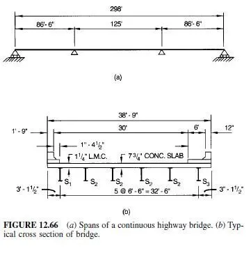
Articles 12.1 and 12.3 recommended use of continuity for multispan bridges. Advantages over simply supported spans include less weight, greater stiffness, smaller deflections, and fewer bearings and expansion joints. Disadvantages include more complex fabrication and erection and often the costs of additional field splices.
Continuous structures also offer greater overload capacity. Failure does not necessarily occur if overloads cause yielding at one point in a span or at supports. Bending moments are redistributed to parts of the span that are not overstressed. This usually can take place in bridges because maximum positive moments and maximum negative moments occur with loads in different positions on the spans. Also, because of moment redistribution due to yielding, small settlements of supports have no significant effects on the ultimate strength of continuous spans. If, however, foundation conditions are such that large settlements could occur, simple-span construction is advisable.
While analysis of continuous structures is more complicated than that for simple spans, design differs in only a few respects. In simple spans, maximum dead-load moment occurs at midspan and is positive. In continuous spans, however, maximum dead-load moment occurs at the supports and is negative. Decreasing rapidly with distance from the support, the negative moment becomes zero at an inflection point near a quarter point of the span.
Between the two dead-load inflection points in each interior span, the dead-load moment is positive, with a maximum about half the negative moment at the supports.
As for simple spans, live loads are placed on continuous spans to create maximum stresses at each section. Whereas in simple spans maximum moments at each section are always positive, maximum live-load moments at a section in continuous spans may be positive or negative. Because of the stress reversal, fatigue stresses should be investigated, especially in the region of dead-load inflection points. At interior supports, however, design usually is governed by the maximum negative moment, and in the midspan region, by maximum positive moment. The sum of the dead-load and live-load moments usually is greater at supports than at midspan. Usually also, this maximum is considerably less than the maximum moment in a simple beam with the same span. Furthermore, the maximum negative moment decreases rapidly with distance from the support.
The impact fraction for continuous spans depends on the length L, ft, of the portion of the span loaded to produce maximum stress. For positive moment, use the actual loaded length. For negative moment, use the average of two adjacent loaded spans.
Ends of continuous beams usually are simply supported. Consequently, moments in threespan and four-span continuous beams are significantly affected by the relative lengths of interior and exterior spans. Selection of a suitable span ratio can nearly equalize maximum positive moments in those spans and thus permit duplication of sections. The most advantageous ratio, however, depends on the ratio of dead load to live load, which, in turn, is a function of span length. Approximately, the most advantageous ratio for length of interior to exterior span is 1.33 for interior spans less than about 60 ft, 1.30 for interior spans between about 60 to 110 ft, and about 1.25 for longer spans.
When composite construction is advantageous (see Art. 12.1), it may be used either in the positive-moment regions or throughout a continuous span. Design of a section in the positive-moment region in either case is similar to that for a simple beam. Design of a section in the negative-moment regions differs in that the concrete slab, as part of the top flange, cannot resist tension. Consequently, steel reinforcement must be added to the slab to resist the tensile stresses imposed by composite action.
Additionally, for continuous spans with a cast-in-place concrete deck, the sequence of concrete pavement is an important design consideration. Bending moments, bracing requirements, and uplift forces must be carefully evaluated.


