Live loads are loads of varying magnitudes and/or positions caused by the use of the structure. Sometimes, the term live loads is used to refer to all loads on the structure that are not dead loads, including environmental loads, such as snow loads or wind loads. However, since the probabilities of occurrence for environmental loads are di¤erent from those due to the use of structures, the current codes use the term live loads to refer only to those variable loads caused by the use of the structure. It is in the latter context that this text uses this term.
The magnitudes of design live loads are usually specified in building codes. The position of a live load may change, so each member of the structure must be designed for the position of the load that causes the maximum stress in that member. Di¤erent members of a structure may reach their maximum stress levels at di¤erent positions of the given load. For example, as a truck moves across a truss bridge, the stresses in the truss members vary as the position of the truck changes. If member A is subjected to its maximum stress when the truck is at a certain position x, then another member B may reach its maximum stress level when the truck is in a di¤erent position y on the bridge. The procedures for determining the position of a live load at which a particular response characteristic, such as a stress resultant or a deflection, of a structure is maximum (or minimum) are discussed in subsequent chapters.
Live Loads for Buildings
Live loads for buildings are usually specified as uniformly distributed surface loads in pounds per square foot or kilopascals. Minimum floor live loads for some common types of buildings are given in Table 2.2.
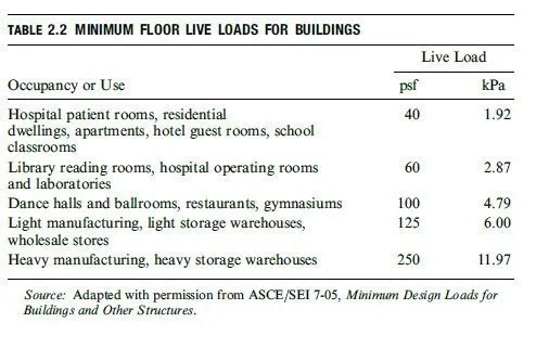
For a comprehensive list of live loads for various types of buildings and for provisions regarding roof live loads, concentrated loads, and reduction in live loads, the reader is referred to the ASCE 7 Standard.
Live Loads for Bridges
Live loads due to vehicular tra°c on highway bridges are specified by the American Association of State Highway and Transportation O°- cials in the Standard Specifications for Highway Bridges [36], which is commonly referred to as the AASHTO Specification. As the heaviest loading on highway bridges is usually caused by trucks, the AASHTO Specification defines two systems of standard trucks, H trucks and HS trucks, to represent the vehicular loads for design purposes. The H-truck loadings (or H loadings), representing a two-axle truck, are designated by the letter H, followed by the total weight of the truck and load in tons and the year in which the loading was initially specified. For example, the loading H20-44 represents a code for a twoaxle truck weighing 20 tons initially instituted in the 1944 edition of the AASHTO Specification. The axle spacing, axle loads, and wheel spacing for the H trucks are shown in Fig. 2.2(a). The HS-truck loadings (or HS loadings) represent a two-axle tractor truck with a single-axle semitrailer. These loadings are designated by the

letters HS followed by the weight of the corresponding H truck in tons and the year in which the loading was initially specified. The axle spacing, axle loads, and wheel spacing for the HS trucks are shown in Fig. 2.2(a). Note that the spacing between the rear axle of the tractor truck and the axle of the semitrailer should be varied between 14 ft and 30 ft, and the spacing causing the maximum stress should be used for design. The particular type of truck loading to be used in design depends on the anticipated tra°c on the bridge. The H20-44 and HS20-44 are the most commonly used loadings; the axle loads for these loadings are shown in Fig. 2.2(a).
In addition to the aforementioned single-truck loading, which must be placed to produce the most unfavorable e¤ect on the member being designed, AASHTO specifies that a lane loading, consisting of a uniformly distributed load combined with a single concentrated load, be considered. The lane loading represents the e¤ect of a lane of mediumweight vehicles containing a heavy truck. The lane loading must also be placed on the structure so that it causes maximum stress in the member under consideration. As an example, the lane loading corresponding to the H20-44 and HS20-44 truck loadings is shown in Fig. 2.2(b). The type of loading, either truck loading or lane loading, that causes the maximum stress in a member should be used for the design of that member. Additional information regarding multiple lanes, loadings for continuous spans, reduction in load intensity, and so on, can be found in the AASHTO Specification.
Live loads for railroad bridges are specified by the American Railway Engineering and Maintenance of Way Association (AREMA) in the Manual for Railway Engineering [26]. These loadings, which are commonly known as Cooper E loadings, consist of two sets of nine concentrated loads, each separated by specified distances, representing the two locomotives followed by a uniform loading representing the weight of the freight cars. An example of such a loading, called the E80 loading, is depicted in Fig. 2.3. The design loads for heavier or lighter trains can be obtained from this loading by proportionately increasing or decreasing the magnitudes of the loads while keeping the same distances
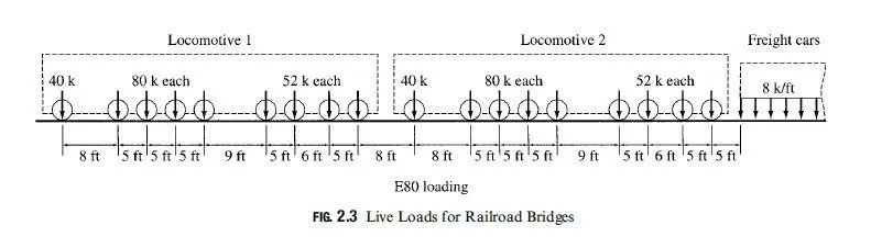
between the concentrated loads. For example, the E40 loading can be obtained from the E80 loading by simply dividing the magnitudes of the loads by 2. As in the case of highway bridges considered previously, live loads on railroad bridges must be placed so that they will cause the most unfavorable e??ect on the member under consideration.