Introduction to Strength Design of Reinforced Shear Walls
In this section, we shall study the behavior and design of reinforced masonry shear walls. The discussion follows the same approach used previously for unreinforced masonry shear walls.
Design Steps for Strength Design of Reinforced
Shear Walls Reinforced masonry shear walls must be designed for the effects of:
1. Gravity loads from self-weight, plus gravity loads from overlying roof or floor levels.
2. Moments and shears from in-plane shear loads.
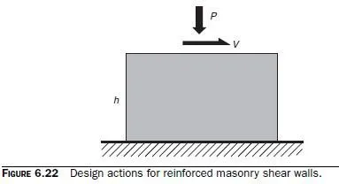
Actions are shown in Fig. 6.22.
Flexural capacity of reinforced shear walls using strength procedures is calculated using moment-axial force interaction diagrams as discussed in the section on masonry walls loaded out-of-plane. In contrast to the elements addressed in that section, a shear wall is subjected to flexure in its own plane rather than out-of-plane. It therefore usually has multiple layers of flexural reinforcement. Computation of momentaxial force interaction diagrams for shear walls is much easier using a spreadsheet.

From the 2008 MSJC Code, Sec. 3.3.4.1.2, nominal shear strength is the summation of shear strength from masonry and shear strength from shear reinforcement:


The nominal resistance from reinforcement is taken as the area associated with each set of shear reinforcement, multiplied by the number of sets of shear reinforcement crossing the hypothetical failure surface. Because the hypothetical failure surface is assumed to be inclined at 45°, its projection along the length of the member is approximately equal to dv, and number of sets of shear reinforcement crossing the hypothetical failure surface can be approximated by (dv/s):

The actual failure surface may be inclined at a larger angle with respect to the axis of the wall, however. Also, all reinforcement crossing the failure surface may not yield. For both these reasons, the assumed resistance is decreased by an efficiency factor of 0.5. From the 2008 MSJC Code, Sec. 3.3.4.1.2.2,
