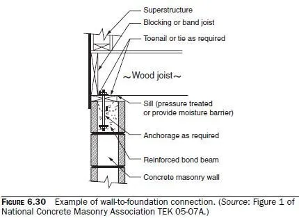
Bearing walls that resist out-of-plane lateral loads, and shear walls, must be designed to transfer lateral loads to the floors above and below. Examples of such connections are shown in Figs. 6.30 through 6.34. These connections would have to be strengthened for regions subject to strong earthquakes or strong winds. Section 1604.8.2 of the 2009 IBC has additional requirements for anchorage of diaphragms to masonry walls. Section 12.11 of ASCE 7-05 has additional requirements for anchorage of structural walls for structures assigned to seismic design categories C and higher.


Wall-to-Foundation Connections
As shown in Fig. 6.31, CMU walls (or the inner CMU wythe of a drainage wall) must be connected to the concrete foundation. Bond breaker should be used only between the outer veneer wythe and the foundation.
Wall-to-Floor Details
Examples of a wall-to-floor detail are shown in Figs. 6.31 and 6.32. In the latter detail (floor or roof planks oriented parallel to walls), the planks are actually cambered. They are shown on the outside of the walls so that this camber does not interfere with the coursing of the units. Some designers object to this detail because it could lead to spalling of the cover. If it is modified so that the planks rest on the face shells of the walls, then the thickness of the topping must vary to adjust for the camber, and form boards must be used against both sides of the wall underneath the planks, so that the concrete or grout that is cast into the bond beam does not run out underneath the cambered beam.
Wall-to-Roof Details
An example of a wall-to-roof detail is shown in Fig. 6.33.
Typical Details of Wall-to-Wall Connections
Typical details of wall-to-wall connections are shown in Fig. 6.34.