Consider the simple structure of Fig. 5.21, the same one whose bearing walls have been designed previously in this book. Use nominal 8-in. concrete masonry units, f ² m = 1500 lb/in.2, and Type S PCL mortar. The roof applies a gravity load of 1050 lb/ft to the walls; the walls measure 16 ft, 8 in. height to the roof, and have an additional 3 ft, 4 in. parapet. The walls are loaded with a wind load of 20 lb/ft2. The roof acts as a one-way system, transmitting gravity loads to the front and back walls. At this stage, all loads are unfactored; load factors will be applied later.
Now design the shear wall. Try an 8-in. wall with face-shell bedding only. The critical section for shear is just under the roof, where axial load in the shear walls is least, coming from the parapet only. As a result of the wind loading, the reaction transmitted to the roof diaphragm is as calculated using Fig. 5.22.

This is divided evenly between the two shear walls, so the shear per wall is 3600 lb.
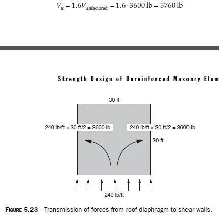
In Fig. 5.23, for simplicity, the lateral load is shown as if it acted on the front wall alone. In reality, it also acts on the back wall, so that the structure is subjected to pressure on the front wall, and suction on the back wall.
The horizontal diaphragm reaction transferred to each shear wall is 240 lb/ft, multiplied by the building width of 30 ft, and then divided equally between the two shear walls, for a total of 3600 lb per shear wall. Using the conservative loading case of 0.9D + 1.6W,

Compute the axial force in the wall at that level. To be conservative, use the loading combination 0.9D + 1.6W. The force acting normal to the shear-transfer plane is
Nu = 0.9 × 3.33 ft ⋅ 48 lb/ft2 ⋅ 30 ft = 4316 lb
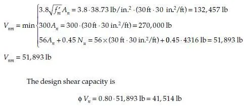
The nominal shear capacity at that level is

The design shear capacity far exceeds the factored design shear of 5760 lb, and the wall is satisfactory for shear. Now check for the net flexural tensile stress. The critical section is at the base of the wall, where in-plane moment is maximum. Because the roof spans between the front and back walls, the distributed gravity load on the roof does not act on the side walls, and their axial load comes from self-weight only. Again, use the conservative loading combination of 0.9D + 1.6W:

The net tension in the wall (actually a compressive stress) is less than the modulus of rupture for Type S PCL mortar and hollow units (63 lb/in.2) times the φ-factor of 0.6 (in other words, 37.8 lb/in.2), and the design is satisfactory.
When the wind blows against the side walls, these walls transfer their loads to the roof diaphragm, and the front and back walls act as shear walls. The side walls must be checked for this loading direction also, following the procedures of previous examples in this book. In-plane, the (h/r) value for this shear wall is much less than the triggering value of 45, and the moment magnifier can be taken as 1.0 (2008 MSJC Code Sec. 3.2.2.4).