This section examines the five primary categories of pipes used in WSDOT projects: drain pipe, underdrain pipe, culvert pipe, storm sewer pipe, and sanitary sewer pipe.
Drain Pipe
Drain pipe is small-diameter pipe (usually less than 24-inch diameter) used to convey roadway runoff or groundwater away from the roadway profile. Drain pipe is not allowed to cross under the roadway profile and is intended for use in easily accessible locations should it become necessary to maintain or replace the pipe. The minimum design life expectancy is 25 years and no protective treatment is required.
Drain pipe applications include simple slope drains and small-diameter “tight lines” used to connect underdrain pipe to storm sewers. Slope drains generally consist of one or two inlets with a pipe conveying roadway runoff down a fill slope. These drain pipes are relatively easy to install and are often replaced when roadway widening or embankment slope grading occurs. Slope drains are most critical during the first few years after installation, until the slope embankment and vegetation have had a chance to stabilize.
Drain pipe smaller than 12 inches in diameter can withstand fill heights of 30 feet or more without experiencing structural failure. All of the materials listed in WSDOT’s Standard Specifications are adequate under these conditions. For drain pipe applications using pipe diameters 12 inches or larger, or with fill heights greater than 30 feet, the PEO shall specify only those materials listed in both the Standard Specifications and the fill height tables in Section 8-12.
8-2.2 Underdrain Pipe
Underdrain pipe is small-diameter perforated pipe intended to intercept groundwater and convey it away from areas such as roadbeds or retaining walls. Underdrain applications use 6- to 8-inch-diameter pipe, but larger diameters can be specified. The minimum design life expectancy is 25 years, and no protective treatment is required. The Standard Specifications list applicable materials for underdrain pipe.
Underdrain pipe is generally used in conjunction with well-draining backfill material and a construction geotextile. Details regarding the various applications of underdrain pipe are described in WSDOT’s Design Manual, the WSDOT Plan Sheet Library, and the Standard Plans. The hydraulic design of underdrain pipe is discussed in Chapter 6.
8-2.3 Culvert Pipe
A culvert is a conduit under a roadway or embankment used to maintain flow from a natural channel or drainage ditch. Culverts are generally more difficult to replace than drain pipe, especially when located under high fills or major highways. Because of this, a minimum design life expectancy of 50 years is required for all culverts. Metal culvert pipes require a protective coating at some locations. Details are described in Section 8-5.3.1.
The maximum and minimum fill heights over a pipe material are provided in Section 8-12. For materials or sizes not provided in Section 8-12, contact the State Hydraulics Office or review the Standard Specifications.
The hydraulic design of culverts is discussed in Chapter 3. In addition to the hydraulic constraints of a location, the final decision regarding the appropriate culvert size may be governed by fish passage requirements, as discussed in Chapter 7.
Culvert shapes, sizes, and applications can vary substantially from one location to another. Listed below is a discussion of the various types of culverts that may appear on a contract.
8-2.3.1 Circular and Schedule Culvert Pipe
Circular culvert pipe measuring 12 to 48 inches in diameter is designated as “schedule pipe” and shall be selected unless a pipe material is excluded for engineering reasons. The pipe schedule table listed in Section 7-02 of the Standard Specifications includes the structurally suitable pipe alternatives available for a given culvert diameter and fill height. Additionally, Figure 8-8, Figure 8-10, and Figure 8-12 provide the PEO with a list of pipe alternatives and protective treatment depending on the corrosion zone. All schedule pipe shall be installed in accordance with Section 8-10.4.
Schedule culvert pipe shall be specified as “Schedule Culv. Pipe in Diam.” On the contract plan sheets. Schedule pipe must be treated with the same protective coatings as other culvert pipe.
The type of material for circular culvert pipe measuring 54 to 120 inches in diameter shall be designated on the plan sheets. The structure notes sheet should include any acceptable alternative material for that particular installation. A schedule table for these large sizes has not been developed because of their limited use. Also, structural, hydraulic, or aesthetic issues may control the type of material to be used at a site, and a specific design for each type of material available is necessary.
8-2.3.2 Pipe Arches
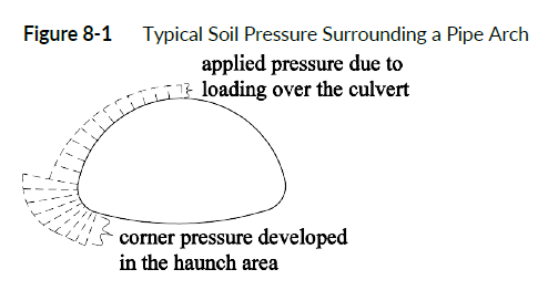
Pipe arches, sometimes referred to as “squash pipe,” are circular culverts that have been reshaped into a structure with a circular top and a flat, wide bottom. For a given vertical dimension, pipe arches provide a larger hydraulic opening than a circular pipe. This can be useful in situations with minimal vertical clearances. Pipe arches also tend to be more effective than circular pipe in low flow conditions (such as fish passage flows) because pipe arches provide most of their hydraulic opening near the bottom of the structure, resulting in lower velocities and more of the main channel being spanned.
The primary disadvantage to using pipe arches is that the fill height range is somewhat limited. Because of the shape of the structure, significant corner pressures are developed in the haunch area as shown in Figure 8-1. The ability of the backfill to withstand the corner pressure near the haunches tends to be the limiting factor in pipe arch design and is demonstrated in the fill height tables shown in Section 8-12.
8-2.3.3 Structural Plate Culverts
Structural plate culverts are steel or aluminum structures delivered to the project site as unassembled plates of material and bolted together. Structural plate culverts are large diameter—from 10 to 40 feet or more—and are available in several different shapes including circular, pipe arch, elliptical, and bottomless arch with footings. These structures are designed to span the main channel of a stream and are a viable option when fish passage is a concern.
The material requirements for structural plate culverts are described in the Standard Specifications. Aluminum structural plate culverts can be used anywhere in the state, regardless of the corrosion zone. Steel structure plate culverts are not permitted in salt water or Corrosion Zone III, as described in Section 8-4. The protective coatings described in Section 8-5.3.1 shall not be specified for use on these types of culverts because the coatings interfere with the bolted seam process.
To compensate for the lack of protective treatment, structural plate furnished in galvanized steel shall be specified with 1.5 ounces per square foot (oz/ft2) of galvanized coating on each plate surface (galvanized culvert pipe is manufactured with 1 oz/ft2 of galvanized coating on each pipe surface). The PEO of structural plate culverts may also add extra plate thickness to the bottom plates to compensate for corrosion and abrasion in high-risk areas. Increasing the gage thickness in this manner can provide a service life of 50 years or more for a small cost increase.
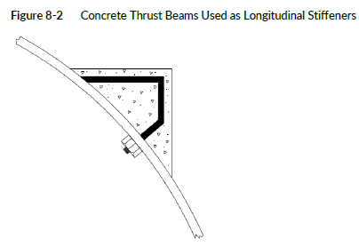
Longitudinal or circumferential stiffeners may be added to prevent excessive deflection due to dead and/or live loads on larger structural plate culverts. Circumferential stiffeners are usually metal ribs bolted to the outside of the culvert. Longitudinal stiffeners may be metal or reinforced concrete thrust beams, as shown in Figure 8-2. The thrust beams are added to the structure prior to backfill. Concrete thrust beams provide circumferential and longitudinal stiffening and a solid vertical surface for soil pressures to act on; the solid surface also facilitates backfilling.
Another method for diminishing loads placed on large-span culverts is to construct a reinforced concrete distribution slab over the top of the backfill above the culvert. The distribution slab is used in low-cover applications and distributes live loads into the soil column adjacent to the culvert. The State Hydraulics Office should be consulted to assist in the design of this type of structure.
8-2.3.4 Private Road Approach and Driveway Culverts
The requirements for culverts placed under private road approaches and driveways are less stringent than the requirements for culverts placed under roadways.
For the purpose of this chapter the terms “access,” “approach,” and “driveway” are referred as “driveway” to remain consistent with the WSDOT Design Manual.
8-2.3.4.1 Applicable Criteria
The requirements in this section apply to a drainage pipe constructed within an existing WSDOT drainage ditch to accommodate and maintain stormwater drainage underneath a driveway. Driveway culverts are off the main line of the highway, so minimal hazard is presented to the traveling public if a failure occurs. The requirements for culverts placed under driveways are less stringent than the requirements for culverts placed under roadways except those identified as fish barriers by WDFW. Fish barrier private road approach and driveway culverts need to follow WDFW water crossing design guidelines. Culverts that cross bioswales are treated in a different manner. See Section 8-2.3.4.7.
8-2.3.4.2 Culvert Replacement
At a minimum, the replacement culvert should have the same size, slope, and material type as the existing culvert. If the culvert is replaced because of the failure of the existing culvert, an appropriate hydraulic evaluation should be done to prevent future problems.
8-2.3.4.3 Construction Material
Within the WSDOT ROW, driveway culverts shall be constructed from material selection guidance as described in Section 8-3.
8-2.3.4.4 Minimum Size
Private road approach and driveway culverts shall be sized to pass the 10-year ditch flow capacity without overtopping the driveway. The minimum size for driveway culverts shall be 12 inches in diameter for round pipe or an equivalent cross-sectional area for arch or elliptical shapes.
8-2.3.4.5 Maximum Length
The length of a culvert will vary depending on the connection width, side slopes, and ditch depth. Use the minimum length of pipe necessary to span a driveway plus allow for appropriate end walls because a longer pipe may get clogged more easily, which frequently creates maintenance problems.
8-2.3.4.6 Minimum Cover
Driveway culverts shall be provided with the minimum cover recommended by the pipe structural design requirements, or 1 foot, whichever is greater. It is difficult to provide a minimum 2-foot cover over the top of these culverts. Therefore, private road approach and driveway culverts can be specified without the protective treatments described in Section 8-5.3.1, and the minimum fill heights listed in Section 8-12 can be reduced to 1 foot (0.3 m).
If live loads approaching AASHTO HS-25 loading will consistently be traveling over the culvert and if the fill height is less than 2 feet, only pipes meeting the minimum fill height described in Section 8-12 shall be specified.
8-2.3.4.7 Culvert End Treatments
All driveway culverts shall be provided with end treatments on the upstream and downstream ends of the culvert to protect and help maintain the integrity of the culvert opening. Headwalls and/or wingwalls and flared end sections are acceptable end treatments.
8-2.3.4.8 Minimum Slope
A minimum slope shall be provided to achieve the minimum velocities outlined in Section 3-3.5.
8-2.3.4.9 Design Documentation of Driveway Culverts
Additional information must be included in the drainage report and on the construction drawings for new developments, where the use of roadside ditches and driveway culverts is proposed. Driveway culverts shall be designed and documented in the development’s drainage report, based on the tributary area at the downstream lot line. The construction drawings shall include information regarding sizes, materials, locations, lengths, grades, and end treatments for all driveway culverts. Typical driveway crossing/culvert details shall be included in the construction drawings. The construction drawings must address the roadside ditch section in detail to ensure that adequate depth is provided to accommodate the driveway culverts, including the minimum cover, and considering overtopping of the driveway when the culvert capacity is exceeded.
If driveways or approach roads cross a bioswale, the culvert should be checked to establish that the backwater elevation would not exceed the banks of the swale. See Section 2-6 for energy dissipation requirements.