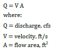
The determination of the flow characteristics for uniform flow conditions can be calculated based on the continuity equation (Equation 4-1). This equation states that the discharge (Q) is equivalent to the product of the channel velocity (V) and the area of flow (A).
While channel geometry can be estimated or surveyed, the flow velocity may not be as practical to manually or directly measure. When actual channel or flow velocity measurements are not available, the velocity can be calculated using the Manning’s equation shown in Equation 4-2.![]()
where:
V = mean velocity of flow in feet per second
R = hydraulic radius in feet (R = area (A) of flow section / wetted perimeter (P) of flow in channel)
S = slope of the energy grade line (EGL) or, for assumed uniform flow, the slope of the channel in feet (vertical) per foot (horizontal), to calculate see points shown in Figure 4-1, Figure 4-2, and Figure 4-3 in following sections, where SUF = (Aus – Bds)/HMDAB), and SUF is the slope for uniform flow conditions, Aus is the elevation at the upstream located Point A, Bds is the elevation at the downstream located Point B, and HMDAB is the horizonal measured distance between Points A and B; for assumed non-uniform flow, see points shown in Figure 4-4, Figure 4-5, and Figure 4-6 in following sections, where SNUF = (Bus – Bds)/HMDBB), and SNUF is the slope of non-uniform flows, Bus is the elevation at the upstream located Point B, Bds is the elevation at the downstream located Point B, and HMDBB is the horizonal measured distance between Points B and B.
n = Manning’s roughness coefficient or friction factor of the channel lining, and refer to Table 4-1.
The flow area of a channel can be determined by previous investigations, surveys, or studies, or can be estimated through measurements of the channel and corresponding flow conditions. Determinations of slope (S) can be directly measured in the field for typical uniform and non-uniform flow conditions; refer to Section 4-3 below for more guidance on measuring in the field. If one or more variables are unknown, the flow area or flow depth must be calculated by trial and error, as presented in HDS-4, or by using a computer hydraulic program, such as the FHWA Hydraulic Toolbox or StormShed. The hydraulic designer is also referred to HDS-4 for further information on channel flow rates and velocities.

