The HGL shall be designed so there is air space between the top of water and the inside of the pipe. In this condition, the flow is operating as gravity flow, and the HGL is the WSEL traveling through the storm sewer system. If the HGL becomes higher than the crown elevation of the pipe, the system will start to operate under pressure flow. If the system is operating under pressure flow, the WSEL in the catch basin/manhole needs to be calculated to verify that the WSEL is below the rim (top) elevation. When the WSEL exceeds the rim elevation, water will discharge through the inlet and cause severe traffic safety problems. Fortunately, if the storm sewer pipes were designed as discussed in the previous sections, then the HGL will only become higher than the catch basin/manhole rim elevation when energy losses become significant or if the cover over a storm sewer is low (less than 5 feet). During the non-storm events (not raining), the HGL must be zero or at the same elevation as the pipe invert; no standing water inside the pipe would be allowed during non-storm events.
Regardless of the design conditions, the HGL should be evaluated when energy loss becomes significant. Possible significant energy loss situations include high flow velocities through the system (greater than 6.6 ft/s), pipes installed under low cover at flat gradients, inlet and outlet pipes forming a sharp angle at structures, and multiple flows entering a structure.
The HGL can be calculated only after the storm sewer system has been designed. When computer models are used to determine the storm sewer capacity, the model will generally evaluate the HGL. The remainder of this section provides the details for how the analysis is performed.
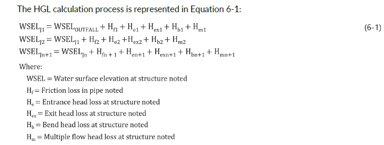
The HGL is calculated beginning at the most downstream point of the storm sewer outlet and ending at the most upstream point. To start the analysis, the WSEL at the storm sewer outlet must be known. Refer to Chapter 3 for an explanation on calculating WSELs at the downstream end of a pipe (the tailwater is calculated the same for the storm sewer outlet and culverts). Once the tailwater/pond elevation is known, the energy loss (usually called head loss) from friction is calculated for the most downstream run of pipe and the applicable minor losses are calculated for the first structure upstream of the storm sewer outlet. Head losses are added to the WSEL at the storm sewer outlet to obtain the WSEL at the first upstream structure (also the HGL at that structure, assuming that velocities are zero in the structure). The head losses are then calculated for the next upstream run of pipe and structure and are added to the WSEL of the first structure to obtain the WSEL of the second upstream structure.
This process is repeated until the HGL has been computed for each structure. The flow in most storm sewers is subcritical; however, if any pipe is flowing supercritical, the HGL calculations are restarted at the structure on the upstream end of the pipe flowing supercritical. (Chapter 4 contains an explanation of subcritical and supercritical flow.)
 If the HGL is lower than the rim elevation of the manhole or catch basin, the design is acceptable. If the HGL is higher than the rim elevation, flow will exit the storm sewer and the design is unacceptable. The most common way to lower the HGL below the rim elevation is to lower the pipe inverts for one or more storm sewer runs or increase the pipe diameter. The HGL shall be designed so that regular maintenance inspections may be achieved without pumping.
Head loss due to friction is a result of the kinetic energy lost as the flow passes through the pipe. The rougher the pipe surface is, the greater the head loss is going to be. Refer to HEC-22 to calculate head loss from friction. Note that for all storm sewer pipes 24 inches or less in diameter, Manning’s n shall be 0.013.
