This section describes culvert design documentation, including hydraulic reports, required field data, and engineering analysis.
3-2.1 Hydraulic Reports
The PEO shall collect field data and perform an engineering analysis as described in Sections 3-2.2 and 3-2.3, respectively. Culverts in this size range shall be referred to on the contract plan sheets as “Schedule Culv. Pipe in. Diam.” The PEO is responsible for listing all acceptable pipe alternatives based on site conditions. The decision regarding which type of pipe material is to be installed at a location will be left to the contractor unless a specific material type is called out in the plans and justification is provided in the hydraulic report. See Chapter 8 for a discussion on schedule pipe and acceptable alternatives.
Culverts larger than 48 inches in diameter or span will be included as part of a specialty report and are required to be designed by either the State Hydraulics Office or a licensed engineer approved by the State Hydraulics Office, as outlined in Chapter 1.
In addition to standard culvert design, the State Hydraulics Office can assist in the design of any unique culvert installation. The requirements for these structures will vary, and the State Hydraulics Office shall be contacted early in the design phase to determine what information will be necessary to complete the engineering analysis.
3-2.2 Required Field Data
Information and field data required to complete an engineering analysis for all new culvert installations or draining an area requiring a culvert shall be part of the hydraulic report and include the items that follow:
• Topographic map showing the contours and the outline of the drainage area
• Description of drainage area ground cover
• Fish passage requirement, if applicable; see Chapter 7
• Soils investigation per WSDOT’s Design Manual
• Proposed roadway profile and alignment in the vicinity of the culvert
• Proposed roadway cross section at the culvert
• Corrosion zone location, pH, and resistivity of the site
• Investigate a sufficient distance upstream and downstream and any other unique features that can affect design, such as low-lying structures that could be affected by excessive headwater debris and anticipated sediment transport
• Other considerations discussed in Section 3-5
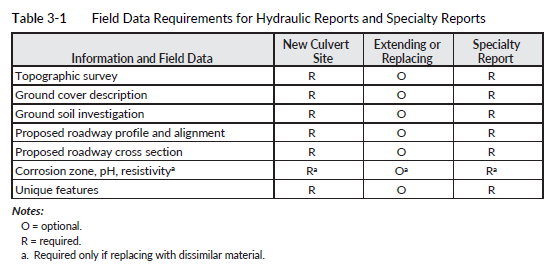
If an existing culvert does not have a history of problems and only needs to be extended or replaced, it is not necessary to gather all the information listed above to determine if it is adequately sized for the flows it receives. Attaining the history of problems at an existing culvert site may be sufficient to complete the analysis. Table 3-1 is a general outline showing the information and field data requirements for a hydraulic report and specialty report.
For culverts with spans between 4 and 20 feet, use the culvert design in this chapter. If the crossing requires fish-bearing design criteria and/or the span is greater than 20 feet, refer to Chapter 7 for further guidance.
Engineering Analysis
Collected field data will be used to perform an engineering analysis. The intent of the engineering analysis is to ensure that the PEO considers several issues, including flow capacity requirements, foundation conditions, embankment construction, runoff conditions, soil characteristics, stream characteristics, potential construction problems, estimated cost, environmental concerns, and any other factors that may be involved and pertinent to the design. Additional analysis may be required, if a culvert is installed for flood equalization, to verify that the difference between the floodwater levels is less than 1 inch on either side of the culvert. The PEO should contact the State Hydraulics Office for further guidance on flood equalization. Other miscellaneous design considerations for culverts are discussed in Section 3-5.
Once the engineering analysis is completed, it will be part of the hydraulic report and shall include the following information:
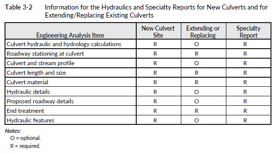
1. Culvert hydrology and hydraulic calculations, as described in Section 3-3 and Table 3-2.
2. Proposed roadway stationing of the culvert location.
3. Culvert length.
4. Culvert diameter. The minimum diameter of culvert pipes under a main roadway shall be 18 inches. Culvert pipe under roadway approaches (i.e., driveway) shall have a minimum diameter of 12 inches.
5. Culvert material.
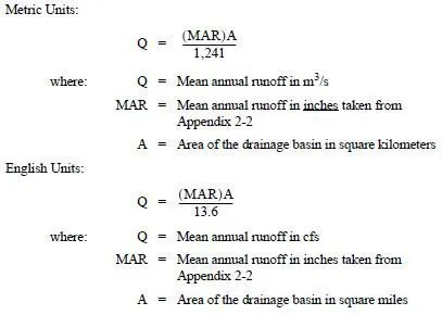
6. Headwater depths, WSELs, and flow rates (Q) for the design flow event (generally the 25-year event and the 100-year flow event).
7. Proposed roadway cross section and roadway profile, demonstrating the maximum and minimum height of fill over the culvert.
8. Appropriate end treatment as described in Section
3-4.
9. Hydraulic features of downstream controls, tailwater, or backwater (storage) conditions.
The information needed for replacement or extension of existing culverts is not the same as that required for new culverts (see Table 3-2). For a more detailed diagnostic about what is required for a specialty report for water crossings, see Chapter 7.