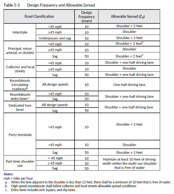
The flow that is not intercepted by an inlet on a continuous grade and continuous run of curb and gutter is considered bypass flow and should be added to the flow traveling toward the next inlet located downstream. The last inlet on a continuous run of curb (that is not a sag or flanking inlet) is permitted to bypass a maximum of 0.1 cfs for the 10-year MRI storm. The bypass flow rate of 0.1 cfs will not usually cause erosion or hydroplaning problems. The PEO shall analyze the spread width of flow after the last inlet on a continuous run of curb until the curb ends or the curb enters into a sump. The spread width analysis shall end at the 50-year WSEL determined in the sag analysis. The spread width shall be compliant with Table 5-1. The spread width requirement also applies to the end of the curb or barrier even without an inlet.
A bypass flow more than 0.1 cfs at the curb or barrier end can be allowed with an approved deviation. To protect the roadside slope downstream of the bypass flow, employ erosion protection measures such as installation of rocks or filter blanket for energy dissipation. Coordinate with the RHE on the slope protection design.
In urban situations, with much lower speeds than noted in Table 5-1, it may not be feasible to use the allowable spread in the Hydraulics Manual. In this situation, the PEO should first consider innovative solutions such as increasing the slope of the gutter (from 2 to 5 percent, for example), depressing the inlet, or using a combination curb opening and grate inlet. If it is still not possible to meet the allowable spread in Table 5-1, the PEO should consider the safety of the intersection, how icing and hydroplaning could affect a driver at this location, and how quickly ponding from the rainfall event will shed off the roadway. The PEO should work with the RHE and traffic engineer to develop a solution that best suits the project location and keeps the roadway safe. If, after considering all possible scenarios, it is determined that the spread of runoff is not safe at this location, then more drastic measures such as revising the project scope or seeking more funding may be necessary.
In addition to the requirements above, in areas where a superelevation transition causes a crossover of gutter flow, the amount of flow calculated at the point of zero superelevation shall be limited to 0.1 cfs. The PEO will find, by the time the roadway approaches the zero point, that the calculated spread (Zd) will become very wide; because of this, the new inlet shall be placed upstream of the zero point. The flow width criteria will be exceeded at the crossover point, even when the flow is less than 0.1 cfs.
Roundabouts are typically designed to accommodate speed limits of 35 miles per hour (mph) or less; generally, the posted advisory speed limits are between 15 and 25 mph. Potentially, runoff from a roundabout is diverted to multiple different directions and, if it is possible, runoff from the upstream roadway should be captured so that flow bypass should be 0.1 cfs or less flowing through the roundabout area. If runoff within a roundabout area is less than 0.1 cfs, no inlets would be necessary. Curb openings could be used to alleviate ponding water at roundabouts. The inlet spacing spreadsheet may not be fully accurate to calculate the flow spread at roundabouts because runoff at a roundabout could flow off in multiple directions. The PEO should coordinate with the RHE and Maintenance to address all possible drainage issues expected with design and construction of the roundabout.

