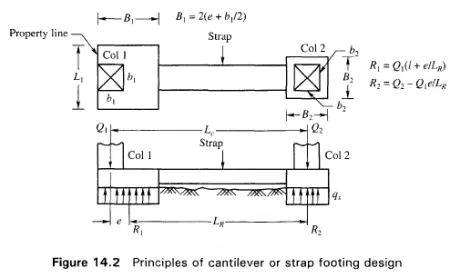
Strap or cantilever footings are designed on the basis of the following assumptions:
1 . The strap is infinitely stiff. It serves to transfer the column loads to the soil with equal and uniform soil pressure under both the footings.
2. The strap is a pure flexural member and does not take soil reaction. To avoid bearing on the bottom of the strap a few centimeters of the underlying soil may be loosened prior to the placement of concrete.
A strap footing is used to connect an eccentrically loaded column footing close to the property line to an interior column as shown in Fig. 14.2.
With the above assumptions, the design of a strap footing is a simple procedure. It starts with a trial value of e, Fig. 14.2. Then the reactions Rl and R2 are computed by the principle of statics. The tentative footing areas are equal to the reactions R{ and R2 divided by the safe bearing pressure q . With tentative footing sizes, the value of e is computed. These steps are repeated until the trial value of e is identical with the final one. The shears and moments in the strap are determined, and the straps designed to withstand the shear and moments. The footings are assumed to be subjected to uniform soil pressure and designed as simple spread footings. Under the assumptions given above the resultants of the column loads Ql and Q2 would coincide with the center of gravity of the two footing areas. Theoretically, the bearing pressure would be uniform under both the footings. However, it is possible that sometimes the full design live load acts upon one of the columns while the other may be subjected to little live load. In such a case, the full reduction of column load from Q2 to R2 may not be realized. It seems justified then that in designing the footing under column Q2, only the dead load or dead load plus reduced live load should be used on column Q1.
The equations for determining the position of the reactions (Fig. 14.2) are

