Culmann’s (1875) method is the same as the trial wedge method. In Culmann’s method, the force polygons are constructed directly on the 0-line AE taking AE as the load line. The procedure is as follows: In Fig. 11.19(a) AB is the retaining wall drawn to a suitable scale. The various steps in the construction of the pressure locus are:
1. Draw 0 -line AE at an angle 0 to the horizontal.
2. Lay off on AE distances, AV, A1, A2, A3, etc. to a suitable scale to represent the weights of
wedges ABV, A51, AS2, AS3, etc. respectively.
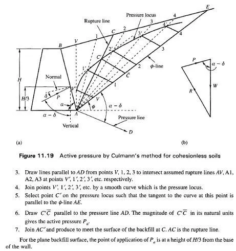
3. Draw lines parallel to AD from points V, 1, 2, 3 to intersect assumed rupture lines AV, Al, A2, A3 at points V”, I’,2′, 3′, etc. respectively.
4. Join points V, 1′, 2′ 3′ etc. by a smooth curve which is the pressure locus.
5. Select point C’on the pressure locus such that the tangent to the curve at this point is parallel to the 0-line AE.
6. Draw C’C parallel to the pressure line AD. The magnitude of C’C in its natural units gives the active pressure Pa.
7. Join AC” and produce to meet the surface of the backfill at C. AC is the rupture line.
For the plane backfill surface, the point of application of Pa is at a height ofH/3 from the base of the wall.