Escalators, or powered stairs, are used when it is necessary to move large numbers of people from floor to floor. They provide continuous movement of persons and can thus remedy traffic conditions that are not readily addressed by elevators. Escalators should be viewed as preferred transportation systems whenever heavy traffic volumes are expected between relatively few floors. Escalators are used to connect airport terminals, parking garages, sports facilities, shopping malls, and numerous mixed-use facilities.
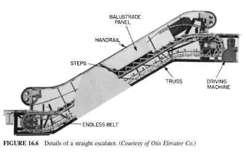
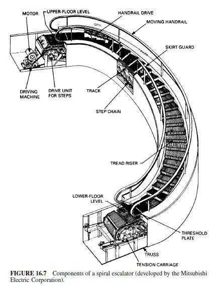
Although escalators generally are used in straight sections (Fig. 16.6), spiral escalators (Fig. 16.7) also are available. Although expensive due to manufacturing complexities, they offer distinct advantages to both the designer and user because of their unique semicircular plan form.
Components of an Escalator
An escalator resembles a powered ramp in construction (Art. 16.2). The major difference is that a powered ramp has a continuous treadway for carrying passengers, whereas the treadway of an escalator consists of a series of moving steps. As for a powered ramp, the installation of powered stairs should conform with the requirements of the American National Standard Safety Code for Elevators, Dumbwaiters, Escalators and Moving Walks, ANSI A17.1.
An escalator consists of articulated, grooved treads and risers attached to a continuous chain moved by a driving machine and supported by a steel truss framework (Fig. 16.6). The installation also includes a handrail on each side of the steps that moves at the same speed as the steps; balustrades, or guards, that enclose the steps on each side and support the handrails; brakes; control devices; and threshold plates at the entrance to and the exit from the treadway. The purpose of the threshold plates is to facilitate smooth passage of passengers between the treadway and landing.
The plates are equipped with a comb, or teeth, that mesh with and are set into grooves in the treadway in the direction of travel, so as to provide firm footing and to minimize the chance that items become trapped between treadway and the landing.
Each step is formed by a grooved tread portion connected to a curved and grooved riser. The tread and riser assembly is either a single die-cast piece or is assembled to a frame. Both are suspended on resilient rollers whose axles are connected to the step chain that moves the steps. The step rollers ride on a set of tracks attached to the trussed framework. The tracks are shaped to allow the step tread to remain horizontal throughout its exposed travel.
Dimensions for Escalators
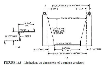
ANSI A17.1 sets the following limitations on escalator steps (Fig. 16.8):
Minimum depth of tread in direction of travel 153â„4 in
Maximum rise between treads 81â„2 in
Minimum width of tread 24 in
Maximum width of tread 40 in
Maximum clearance between tread and adjacent skirt panel 3â„8 in
Maximum distance between handrail centerlines width between balustrades plus 6 in with not more than 3 in on either side of the escalator (see Fig. 16.8b)
The escalator width is measured on the incline between balustrades, as indicated in Fig. 16.8b.
It should be at least as wide as the step but not more than 13 in wider than the step.
Safety Devices for Escalators
To provide a firm footing, treads are grooved in the direction of travel. The grooves mesh with the combs or teeth of the threshold plates at top and bottom of the escalator.
The handrails, which move in synchronization with the steps, should be between 30 and 34 in above the treads. The handrails should extend at normal height at least 12 in beyond the line of points of the combplate teeth. The balustrades carrying the handrails and acting as a guard to prevent passengers from falling off the sides of the moving steps should be designed to resist simultaneous application of a horizontal load of 40 lb / ft and a vertical load of 50 lb / ft, both applied to the top of the balustrades.
The driving machine may be connected to the main drive shaft by toothed gearing, a coupling, or a chain. Step movement is halted by an electrically released, mechanically applied brake, located either on the driving machine or on the main drive shaft. The brake is activated automatically when a power failure occurs, when the treadway or a handrail breaks, or when a safety device is activated.
Safety devices required for escalators include switches for starting, emergency stopping, and maintenance stopping and an electromechanical speed governor that will prevent the step speed from exceeding the maximum design speed. An emergency stop button, protected against accidental activation, is required to be set in the right-hand (when facing the escalator) newel at the top and bottom landings.
