For an ideally straight, exactly concentrically loaded beam or column, only a small force may be needed from an intermediate brace to reduce the unbraced length of a column or the unsupported length of the compression flange of a beam. But there is no generally accepted method of calculating that force.
The principal function of a brace is to provide a node in the buckled configuration.
Hence, rigidity is the main requirement for the brace. But actual members do contain nonuniform residual stresses and slight initial crookedness and may be slightly misaligned, and these eccentricities create deformations that must be resisted by the brace.
A rule used by some designers that has proved satisfactory is to design the brace for 2% of the axial load of columns, or 2% of the total compressive stress in beam flanges. Studies and experimental evidence indicate that this rule is conservative.
Column Bracing
Interior columns of a multistory building are seldom braced between floor connections.
Bracing of any kind generally interferes with occupancy requirements and architectural considerations. Since the slenderness ratio l / r in the weak direction usually controls column size, greatest economy is achieved by using only wideflange column sections or similar built-up sections.
It is frequently possible to reduce the size of wall columns by introducing knee braces or struts in the plane of the wall, or by taking advantage of deep spandrels or girts that may be otherwise required. Thus the slenderness ratio of the weak and strong axis can be brought into approximate balance. The saving in column weight may not always be justified; one must take into account the weight of additional bracing and cost of extra details.
Column bracing is prevalent in industrial buildings because greater vertical clearances necessitate longer columns. Tall slender columns may be braced about both axes to obtain an efficient design.
Undoubtedly, heavy masonry walls afford substantial lateral support to steel columns embedded wholly or partly in the wall. The general practice, however, is to disregard this assistance.
An important factor in determining column bracing is the allowable stress or load for the column section (Art. 7.19). Column formulas for obtaining this stress are based on the ratio of two variables, effective length Kl and the physical property called radius of gyration r.
The question of when to brace (to reduce the unsupported length and thus slenderness ratio) is largely a matter of economics and architectural arrangements; thus no general answer can be given.
Beam Bracing
Economy in size of member dictates whether laterally unsupported beams should have additional lateral support between end supports. Lateral support at intermediate points should be considered whenever the allowable stress obtained from the reduction formulas for large l / rt falls below some margin, say 25%, of the stress allowed for the fully braced condition. There are cases, however, where stresses as low as 4.0 ksi have been justified, because intermediate lateral support was impractical.
The question often arises: When is a steel beam laterally supported? There is no fixed rule in specifications (nor any intended in this discussion) because the answer requires application of sound judgment based on experiences. Tests and studies that have been made indicate that it takes rather small forces to balance the
lateral thrusts of initial buckling.
Figure 7.21 illustrates some of the common situations encountered in presentday practice. In general, positive lateral support is provided by:
(a) and (b) All types of cast-in-place concrete slabs (questionable for vibrating loads and loads hung on bottom flange).
(c) Metal and steel plate decks, with welded connections.
(d) Wood decks nailed securely to nailers bolted to the beam.
(e) and (Æ’) Beam flange tied or braced to strut system, either as shown in (e)
or by means of cantilever tees, as shown in (Æ’); however, struts should be adequate to resist rotation.
(g) Purlins used as struts, with tees acting as cantilevers (common in rigid frames and arches). If plate stiffness are used, purlins should be connected to them with high-strength bolts to ensure rigidity.
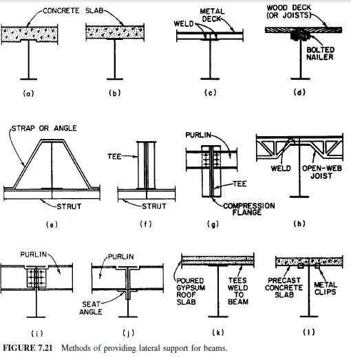
(h) Open-web joists tack-welded (or the equivalent) to the beams, but the joists themselves must be braced together (bridging), and the flooring so engaged with the flanges that the joists, in turn, are adequately supported laterally.
(i) Purlins connected close to the compression flange.
(k) Tees (part of cast-in-place gypsum construction) welded to the beams.
Doubtful lateral support is provided by:
( j ) Purlins seated on beam webs, where the seats are distant from the critical flange
(l ) Precast slabs not adequately fastened to the compression flange.
 The reduction formulas for large l / r, given in Fig. 731 do not apply to steel beams fully encased in concrete, even though no other lateral support is provided.
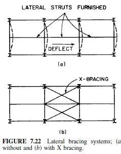
Introducing a secondary member to cut down the unsupported length does not necessarily result in adequate lateral support. The resistive capacity of the member and its supports must be traced through the system to ascertain effectiveness.
For example the system in Fig. 7.22a may be free to deflect laterally as shown. This can be prevented by a rigid floor system that acts as a diaphragm, or in the absence of a floor, it may be necessary to X-brace the system as shown in Fig. 7.22b.
