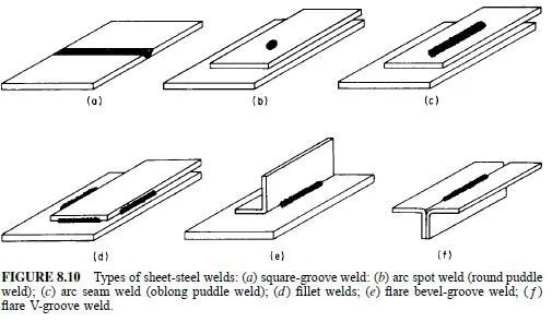
Arc welding may be done in the shop or in the field. The basic sheet-steel weld types are shown in Fig. 8.10. Factors favoring arc welding are portability and versatility of equipment as well as freedom in joint design. Only one side of a joint need be accessible, and overlap of parts is not required if joint fit-up is good.
Helpful Hints for Welding
Distortion may occur with lightweight steel weldments, but it can be minimized by avoiding overwelding. Weld sizes should be matched with service requirements.
Always design welded joints to minimize shrinking, warping, and twisting. Jigs and fixtures for holding lightweight work during welding should be used to control distortion. Directions and amounts of distortion can be predicted and sometimes counteracted by preangling the parts. Discrete selection of weld sequence can also be used to control distortion.
Groove welds (made by butting sheet edges together, Fig. 8.10a) can be designed for 100% joint efficiency. Calculation of design stress is usually unnecessary if the weld penetrates 100% of the section.
Stresses in fillet welds should be considered as shear on the throat for any direction of applied stress. The dimension of the throat is calculated as 0.707 times the length of the shorter leg of the weld. For example, a 12-in-long, 1/4-in-fillet weld has a leg dimension of 1/4 in, a throat of 0.177 in, and an equivalent area of 2.12 in2. For all grades of steel, fillet and plug welds should be proportioned according to the AISI specification for the allowable stress design method; the safety
factor is 2.50, unless otherwise noted.
Types of Arc Welding
Shielded metal arc welding, also called manual stick electrode, is the most common arc-welding process because of its versatility. The method, however, requires skilled operators. The welds can be made in any position, but vertical and overhead welding should be avoided when possible.
Gas metal arc welding uses special equipment to feed a continuous spool of bare or flux-cored wire into the arc. A shielding gas such as argon or carbon dioxide is used to protect the arc zone from the contaminating effects of the atmosphere.
The process is relatively fast, and close control can be maintained over the deposit.
The process is not applicable to materials 1/32 in thick but is extensively used for thicker steels.
Gas tungsten arc welding operates by maintaining an arc between a nonconsumable tungsten electrode and the work. Filler metal may or may not be added. Close control over the weld can be maintained. This process is not widely used for highproduction fabrication, except in specialized applications, because of higher cost.
One form of spot welding is an adaptation of gas metal arc welding wherein a special welding torch and automatic timer are employed. The welding torch is positioned on the work and a weld is deposited by burning through the top layer of the lap joint. The filler wire provides sufficient metal to fill the hole, thereby fusing together the two parts. Access to only one side of the joint is necessary.
Field welding by unskilled operators is feasible. This makes the process advantageous.
Another form of arc spot welding utilizes gas tungsten arc welding. The heat of the arc melts a spot through one of the sheets and partly through the second. When the arc is cut off, the pieces fuse. No filler metal is added.
Design of arc-welded joints of sheet steel is also treated in the AmericanWelding Society Specification for Welding Sheet Steel in Structures, AWS D1.3.
Groove Welds in Butt Joints
The maximum load for a groove weld in a butt joint, welded from one or both sides, should be determined on the basis of the lower-strength base steel in the connection, provided that an effective throat equal to or greater than the thickness of the material is consistently obtained.
Arc Spot Welds
Arc spot welds (Fig. 8.10b), also known as puddle welds, are permitted for welding sheet steel to thicker supporting members in the flat position. Such welds, which result when coalescence proceeds from the surface of one sheet into one or more other sheets of a lapped joint without formation of a hole, should not be made on steel where the thinnest connected part is more than 0.15 in thick, or through a combination of steel sheets having a total thickness exceeding 0.15 in. Arc spot welds are specified by minimum effective diameter of fused area, de. Minimum effective allowable diameter is 3/8 in. The nominal shear load Pn, kips, on each arc spot weld between sheet or between sheets and a supporting member should not exceed the smaller of the values given by Eqs. (8.25) to (8.28).
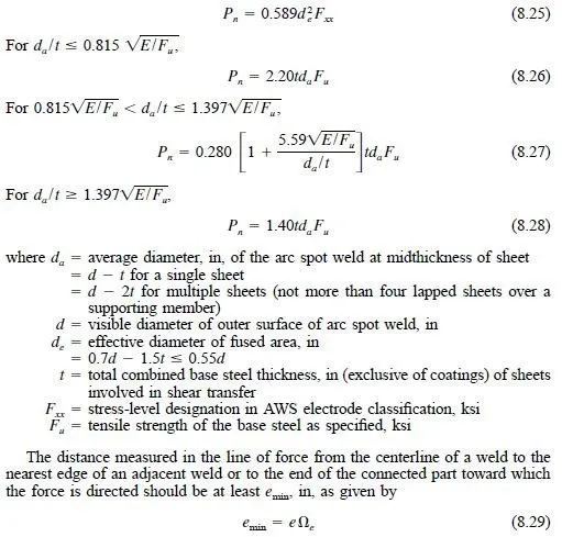
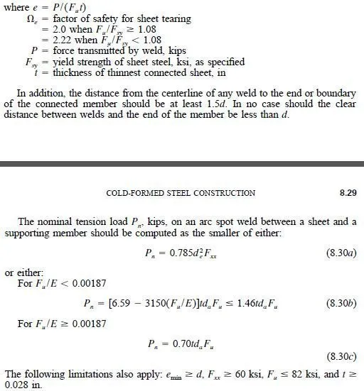
As for arc spot welds (Art. 8.16.4), if measurements indicate that a given weld procedure will consistently give larger diameters da or de, as applicable, the larger diameter may be used to calculate the maximum allowable load, if that procedure will be used.
Arc Seam Welds
These are basically the same as arc spot welds but are made linearly without slots in the sheets (Fig. 8.10c). Arc seam welds apply to the following types of joints:
1. Sheet to a thicker supporting member in the flat position
2. Sheet to sheet in the horizontal or flat position
The shear load Pn, kips, on an arc seam weld should not exceed the values given by either Eq. (8.31) or (8.32).
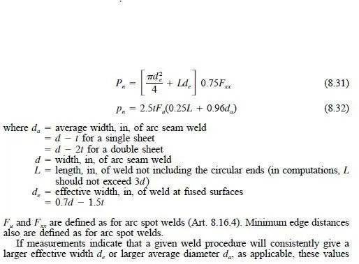
may be used to calculate the maximum allowable load on an arc seam weld, if that welding procedure will actually be used.
Fillet Welds
These are made along the edges of sheets in lapped or T joints (Fig. 8.10d). The
fillet welds may be made in any position and either sheet to sheet or sheet to thicker
steel member.
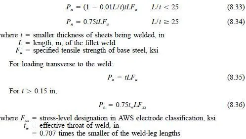
The shear load Pn, kips, on a fillet weld in lapped or T joints should not exceed
the value of Pn computed from Eqs. (8.33) to (8.34).
For longitudinal loading along the weld:
Flare Groove Welds
These are made on the outsides of curved edges of bends in cold-formed shapes (Fig. 8.10e and Æ’). The welds may be made in any position to join:
1. Sheet to sheet for flare V-groove welds
2. Sheet to sheet for flare bevel-groove welds
3. Sheet to thicker steel member for flare bevel-groove welds.
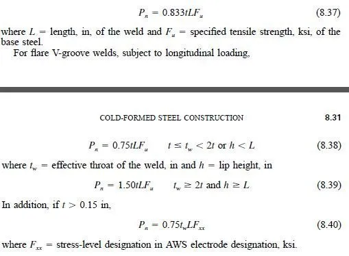
The shear load Pn, kips, on a weld is governed by the thickness t, in, of the sheet adjacent to the weld. The load should not exceed the values of Pn given by Eqs. (8.37) to (8.40).
For flare bevel-groove welds subject to transverse loading,
