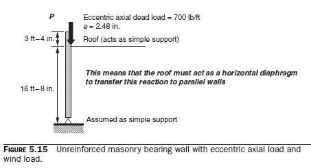
uniformly distributed wind load of 25 lb/ft2. The wall is as shown in Fig. 5.15. At each horizontal plane through the wall, the following conditions must be met:
Maximum compressive stress from factored axial loads must not exceed the slenderness-dependent values in Eqs. (3-12) or (3-13) as appropriate, reduced by a φ-factor of 0.60.
Maximum compressive stress from factored loads (including a moment magnifiers) must not exceed 0.80 f ² m in the extreme compression fiber, reduced by a φ-factor of 0.60.
Maximum tension stress from factored loads (including a moment magnifier) must not exceed the modulus of rupture in the extreme tension fiber, reduced by the φ-factor of 0.60.
For each condition, the more critical of the two possible loading combinations must be checked. Because there is wind load, and because the two previous examples showed little problem with the first two criteria, the third criterion (net tension) may well be critical. For this criterion, the critical loading condition could be either 1.2D + 1.6L, or 0.9D + 1.6W. Both loading conditions must be checked. We must check various points on the wall. Critical points are just below the roof reaction (moment is high and axial load is low, so net tension may govern); at the mid-height of the wall, where moment from eccentric gravity load and wind load are highest; and at the base of the wall (axial load is high, so the maximum compressive stress may govern). Check each of these locations. To avoid having to check a large number of loading combinations and potentially critical locations, it is worthwhile to assess them first, and check only the ones that will probably govern. Due to wind only, the unfactored moment at the base of the parapet (roof level) is

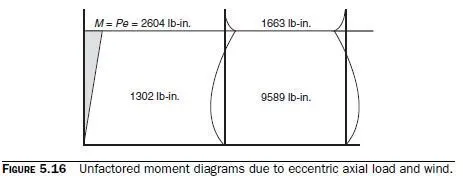
Unfactored moment diagrams due to eccentric axial load and wind are as shown in Fig. 5.16. From the example of Sec. 5.2.4, we know that loading combination 1.2D + 1.6L was not close to critical directly underneath the roof. Because the wind-load moments directly underneath the roof are not very large, they will probably not be critical either. The critical location will probably be at mid-height; the critical loading condition will probably be 0.9D + 1.6W; and the critical criterion will probably be net tension, because this masonry wall is unreinforced.


As before, try 8-in. nominal units, and a specified compressive strength, fm², of 1500 lb/in.2. This can be satisfied using units with a net-area compressive strength of 1900 lb/in.2, and Type S PCL mortar. Work with a strip with a width of 1 ft (measured along the length of the wall in plan). Stresses are calculated using the critical section, consisting of the bedded area only (2008 MSJC, Sec. 1.9.1.1). Now check the net tensile stress. At the mid-height of the wall, the axial force due to 0.9D is

The maximum tensile stress exceeds the prescribed value, and the design is not satisfactory. It will be necessary to grout the wall. The wall weight will increase somewhat, increasing the stress from factored dead load; the factored wind moments will remain unchanged; the section modulus of the wall will increase; and the modulus of rupture of the wall will increase from 63 to 163 lb/in.2.

The wall would have to be thickened to 10 in. or reinforced. Finally, the moment magnifier would have to be checked. Because we know that we have to thicken the wall, and the moment magnifier would make things worse, the calculation is not done here.