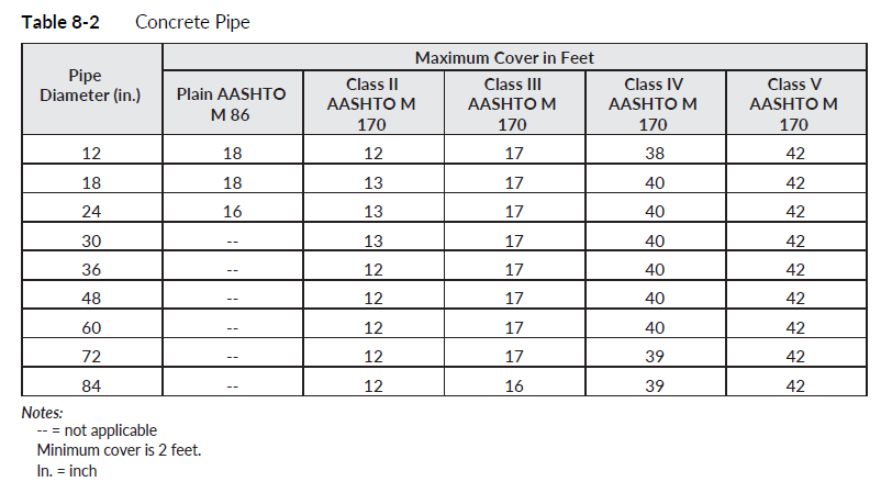
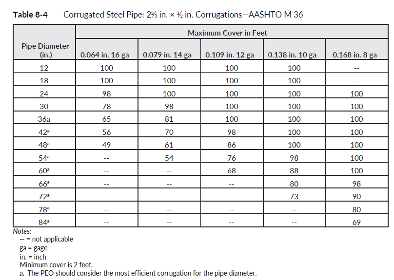
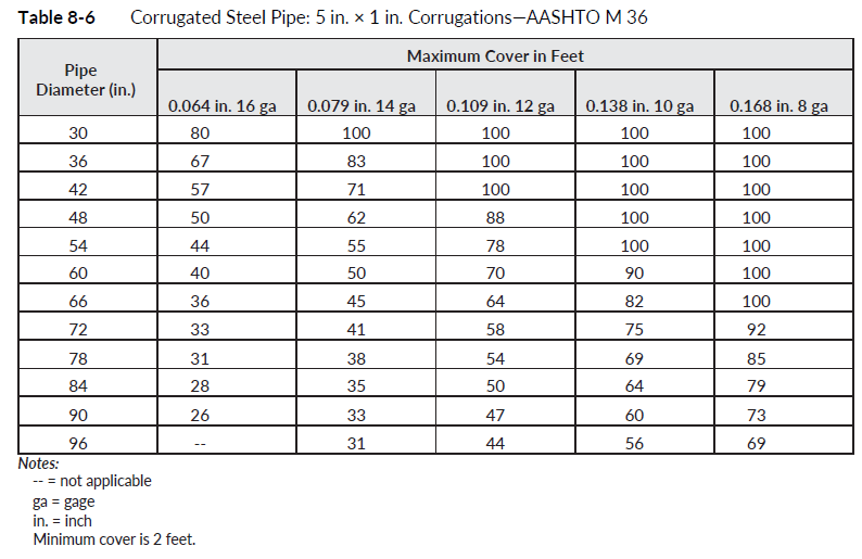
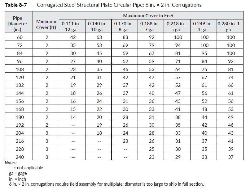
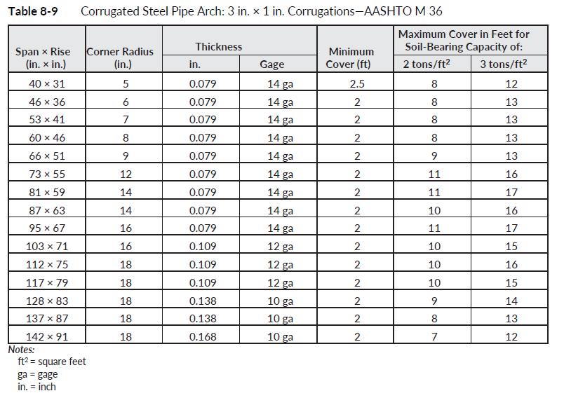
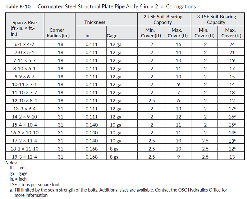
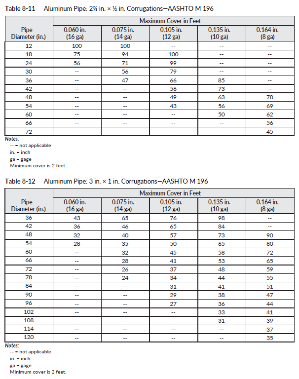
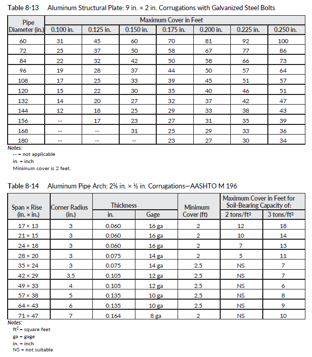
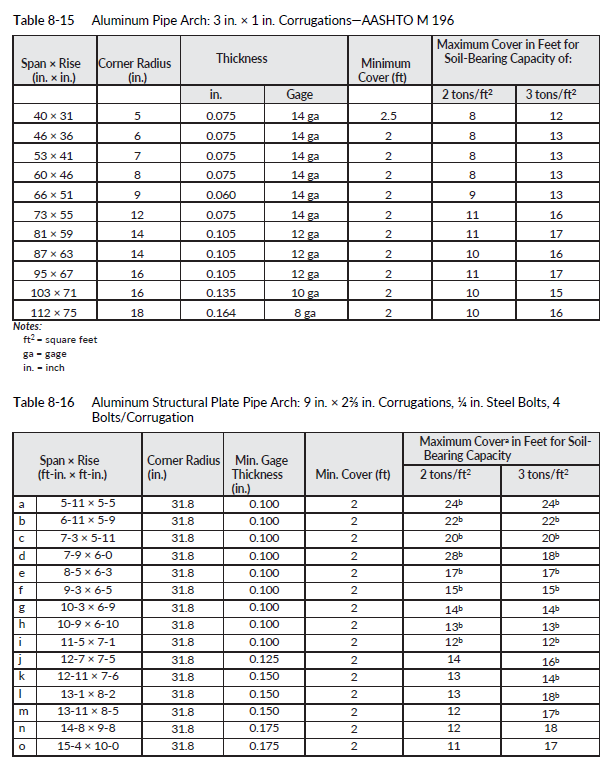
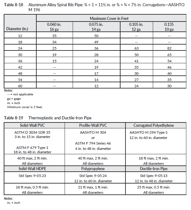
The State Hydraulics Office, using currently accepted design methodologies, has performed a structural analysis for the various types of pipe material available. The results are shown in the fill height tables at the end of this section (Table 8-2 through Table 8-19). The fill height tables demonstrate the maximum and minimum amounts of cover that can be placed over an existing or new pipe, assuming that the pipe is installed in accordance with WSDOT specifications. All culverts, storm sewers, and sanitary sewers shall be installed within the limitations shown in the fill height tables.
The PEO shall specify the same wall thickness or class of material for the entire length of a given pipe, and that specification will be based on the most critical load configuration experienced by any part of the pipe. This will negate the necessity of removing structurally inadequate pipe sections at some point in the future should roadway widening occur. Additionally, when selecting corrugated pipe, the PEO should review all of the tables in Section 8-12.3 and select the most efficient corrugation thickness for the pipe diameter. For fill heights in excess of 100 feet, coordination with the HQ Geotechnical, Bridge and Structures, and Hydraulics Offices is required for review and approval.
When a pipe is rehabilitated with a liner, the liner must be able to withstand the loads without the host pipe included in the calculations.
8-12.1 Pipe Cover
Pipe systems shall be designed to provide at least 2 feet of cover over the pipe, measured from the outside diameter of the pipe to the bottom of pavement. This measurement does not include any asphalt or concrete paving above the top course. Unless the contract plans specify a specific pipe material, the PEO shall plan for the schedule pipe fill heights as described in the Standard Specifications. If there is no possibility of a wheel load over the pipe, a PEO may request using non-scheduled pipe with approval from the State Hydraulics Office through a deviation.
During construction, more restrictive fill heights are required, and are specified in the Standard Specifications. The restrictive fill heights are intended to protect pipe from construction loads that can exceed typical highway design loads.
8-12.1.1 Pipe Sleeve
The pipe shall be sleeved when it is located underneath railroad guideways. The sleeves must be able to withstand the dead and live loads. The sleeve must be extended 10 feet out from the edge of the guideway.
8-12.2 Shallow Cover Installation
In some cases, it is not possible to lower a pipe profile to obtain the necessary minimum cover. In those cases, pipe of the class shown in Table 8-19 may be specified. Included in that table are typical pipe wall thicknesses for a given diameter. The pipe wall thickness must be taken into consideration in low cover applications.
In addition to circular pipe, concrete box culverts and concrete arches are available for use in shallow cover installations. For three-sided or box concrete culverts, the PEO must verify that the shallow cover will still provide HS 25 loading. Other options include ductile-iron pipe, plain steel pipe, PP pipe, or the placement of a concrete distribution slab. The PEO should consult with either the RHO/contact or the State Hydraulics Office for additional guidance on the use of these structures in this application.
8-12.3 Fill Height Tables
Table 8-2 through Table 8-19 are fill height tables.