Along with determining the required pipe sizes for flow conveyance and the HGL, storm sewer system design should consider the following guidelines:
• Soil conditions: Soil with adequate bearing capacity must be present to interact with the pipes and support the load imparted by them. Surface and subsurface drainage must be provided to ensure stable soil conditions. Soil resistivity and pH must also be known so that the proper pipe material will be used. Section 8-5 contains further guidance.
• Structure spacing and capacity: Design guidelines for inlet spacing and capacity aredetailed in
Chapter 5. Structures (catch basins, grate inlets, and manholes) should be placed at all breaks in grade and horizontal alignment. The desired pipe run length between structures is 150 feet and shall not exceed 300 feet for pipes less than 48 inches in diameter and 500 feet for pipes greater than 48 inches in diameter. When grades are flat, pipes are small, or there could be debris issues, the PEO should reduce the spacing. The RHE and local WSDOT Maintenance Office shall be consulted for final determination on maximum spacing requirements. For minimum clearance between culverts and utilities, PEOs should consult the RHE for guidance.
• Existing systems: Criteria for repair and/or replacement of existing systems be provided in future revisions to the Hydraulics Manual. Until then, contact the RHE for guidance when working with existing systems, and refer to Chapter 8 for guidance on trenchless pipe repair methods.
• Future expansion: If a storm sewer system may be expanded in the future, provision for the expansion shall be incorporated into the current design. Additionally, prior to expanding an existing system, the existing system shall be inspected for structural integrity and hydraulic capacity using the Rational Method.
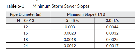
• Velocity: The design velocity for storm sewers shall be between 3 and 10 ft/s. This velocity is calculated using Manning’s equation, under full flow conditions even if the pipe is flowing only partially full with the design storm. The minimum slope required to achieve these velocities is summarized in Table 6-1.
When flows drop below 3 ft/s, pipes can clog because of siltation. Flows can be designed to as low as 2.5 ft/s with justification in the hydraulic report. As the flow approaches (and exceeds) 10 ft/s, PEOs should consult the RHE for abrasion design guidance.
Pipe elevations at structures: Pipe crowns differing in diameter, branch, or trunk lines shall be at the same elevation when entering structures. For pipes of the same diameter where a lateral is placed so the flow is directed against the main flow through the manhole or catch basin, the lateral invert must be raised to match the crown of the inlet pipe. Matching the crown elevation of the pipes will prevent backflow in the smaller pipe. (A crown is defined as the highest point of the internal surface of the transverse cross section of a pipe.) It is also generally acceptable to have the crown elevation of the upstream pipe in the structure be higher than the crown elevation of the downstream pipe in the same structure. Invert elevations of pipe draining a structure shall not be higher than any pipe discharging flow into the same structure unless a stilling structure is an intentional part of the storm sewer design.
• Minimum pipe diameter: The minimum pipe inside diameter shall be 12 inches. If partially replacing or modifying an existing storm sewer system, the new or added storm sewer shall have at least the same diameter as the existing storm sewer even if the hydraulic analysis shows a smaller-diameter storm sewer would meet hydraulic design requirements in that location. If an existing culvert is replaced and converted to a configuration that would classify it as a storm sewer, coordinate with the RHE on the pipe sizing.
• Structure constraints: During the storm sewer layout design, PEOs should also consider the physical constraints of the structure. Specifically:
• Diameter: Verify the maximum allowable pipe diameter into a drainage structure prior to design. Standard Plans for drainage structures have pipe allowances clearly stated in tables for various pipe materials.
• Angle: Verify that the layout is constructible with respect to the angle between pipes entering or exiting a structure before finalizing the storm sewer layout. That is, to maintain structural integrity minimum clearance requirements must be met depending on the pipe diameter. PEOs can verify the minimum pipe angle with the Pipe Angle Calculation Worksheet.
• Pipe material: Storm sewers shall be designed to include all Schedule A pipe options, unless specific site constraints limit options (see Section 6-8 for further discussion).
• Increase in profile grade: In cases where the roadway or ground profile grades increase downstream along a storm sewer, a smaller-diameter pipe may be sufficient to carry the flow at the steeper grade. However, because of maintenance concerns, WSDOT design practices do not allow pipe diameters to decrease in downstream runs. Consideration could be given to running the entire length of pipe at a grade steep enough to allow use of the smaller-diameter pipe. Although this will necessitate deeper trenches, the trenches will be narrower for the smaller pipe and therefore the excavation may not substantially increase. A cost analysis is required to determine whether the savings in pipe costs will offset the cost of any extra structure excavation.
• Discharge location: A discharge location is where stormwater from WSDOT highways is conveyed off of the ROW by pipe, ditch, or other constructed conveyance. Additional considerations for discharge locations include energy dissipators and tidal gates. Energy dissipators prevent erosion at the discharge location. Based on the outlet velocity at the discharge location, the PEO shall install energy dissipation per Section 3-4.7. Installation of tide gates may be necessary when the discharge location is in a tidal area; consult the RHE for further guidance.
• Location: Wide medians usually offer the most desirable storm sewer location. In the absence of a wide median, a location beyond the pavement edge on state ROW or easement is preferable. When a storm sewer is placed beyond the pavement edge, a one-trunk system with connecting laterals shall be used instead of running two separate trunk lines down each side of the road.
Confined space and structure depths: PEOs shall consult the local WSDOT Maintenance Office and RHE to ensure that structures can be adequately maintained.