By definition, a sag is any portion of the roadway where the profile changes from a negative grade to a positive grade. Inlets at sag locations perform differently from inlets on a continuous grade and therefore require a different design criterion. Theoretically, inlets at sag locations may operate in one of two ways: (1) at low ponding depths, the inlet will operate as a weir, or (2) at high ponding depths (5-inch depth above the grated inlet and 1.4 times the grate opening height for combination inlets), the inlet will operate as an orifice. It is very rare that ponding on a roadway will become deep enough to force the inlet to operate as an orifice. As a result, this section focuses on inlets operating as a weir with flow spilling in from the three sides of the inlet that are exposed to the ponding.
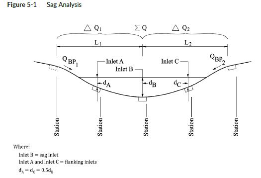
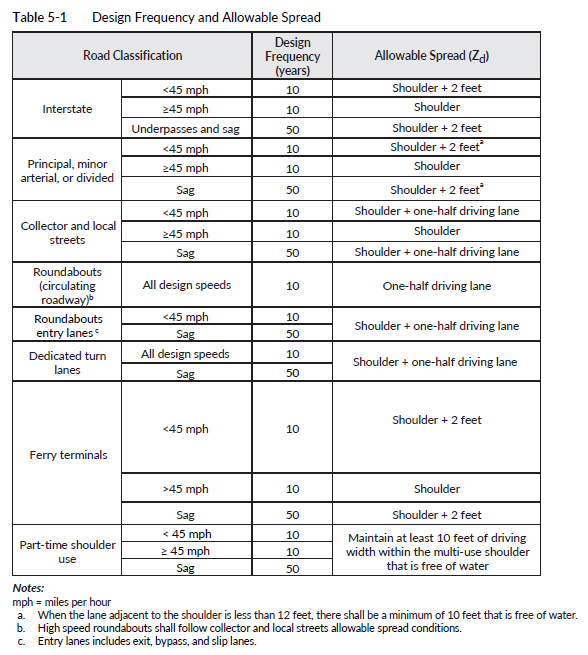
Inlets at sag locations can easily become plugged with debris; therefore, it is good engineering practice to provide some type of relief. This relief can be accomplished by locating flanking inlets, on either side of the sag inlet, so they will operate before water exceeds the allowable spread into the travel lane at the sag. Flanking inlets shall be located so that the depth of water at the flanking inlets ponds to half the allowable depth at the sag (or 0.5dB allowable); see Figure 5-1 above. Flanking inlets are required only when the sag is located in a depressed area and water has no outlet except through the system. A tall curb, traffic barrier, retaining wall, or other obstruction that prevents the runoff from flowing off of the traveled roadway generally represents this condition because it contains this ponded area. However, if runoff is capable of overtopping the curb and flowing away from the roadway before exceeding the allowable sag limits noted in Table 5-1 above, flanking inlets are not required. With this situation, there is a low potential for danger to the drivers of the roadway if the inlets do not function as designed. Before flanking inlets are removed in this situation, the PEO should consider the potential damage of water going over the curb. The PEO shall use the guidelines provided in this section for locating flanking inlets. If the PEO suspects that flanking inlets are unnecessary, consult the RHE earlier in the design.
 Once an inlet has been placed in a sag location, the total actual flow to the inlet can be determined as shown below. qTotal must be less than Qallowable, as described in Equation 5-1.
QTOTAL = QBP1 + QBP2 + ?Q1 +?Q2
where:
QBP1&2 = bypass flow from the last inlet on either side of a continuous grade
?Q1&2 = runoff that is generated from last inlet on either side of the continuous grades; see Figure 5-1.
The effective perimeter of the flanking and sag inlets can be determined using the lengths and widths for various grates provided in Table 5-2. This would be the sum of the three sides of the inlet where flow spills in and where ponding would occur. Only the sides that receive gutter flow (see Figure 5-1) would be assumed to be 50 percent plugged (except for the Combination Inlet, Standard Plan B-25.20-02, which should be considered 0 percent plugged). This will be the grate widths (and not grate length) that are reduced by 50 percent. The total available perimeter that would receive flow is represented by Equation 5-2. This adjustment is in addition to reducing the perimeter to account for the obstruction caused by the bars in the grate. Table 5-2 lists perimeters for various grates with reductions already made for bars.
![]()
where:
Pn = effective perimeter of the “n” (sag or flanking inlet)
L = length of the inlet “n” from Figure 5-1
W = width of the inlet “n” from Figure 5-1
The allowable capacity of an inlet operating as a weir, that is the maximum Qallowable, can be found depending on the inlet layout as described below:
When there is only a single inlet at the sag (no flanking inlets), Equation 5-3 should be used: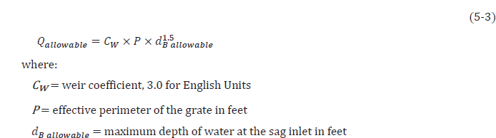
Cw = weir coefficient, 3.0 for English Units
P = effective perimeter of the grate in feet
dBallowable= maximum depth of water at the sag inlet in feet
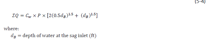
Flanking inlets shall be located laterally from the sag inlet at a distance equal to that required to produce a depth of 0.5???????? ????????????????????????????????????. ???????????????????????????????????????? can be simplified to Equation 5-4 below. Equation 5-4 assumes that all grates are the same size and are oriented the same (all rotated or not rotated):
In some applications, locating inlets so water ponds to 0.5 Qallovable is too long of a distance (generally in cases with long flat slopes). The PEO should instead calculate ???????????????????????????????????????? using Equation 5-5 and check that the spread width of surface water does not exceed those noted in Table 5-1.
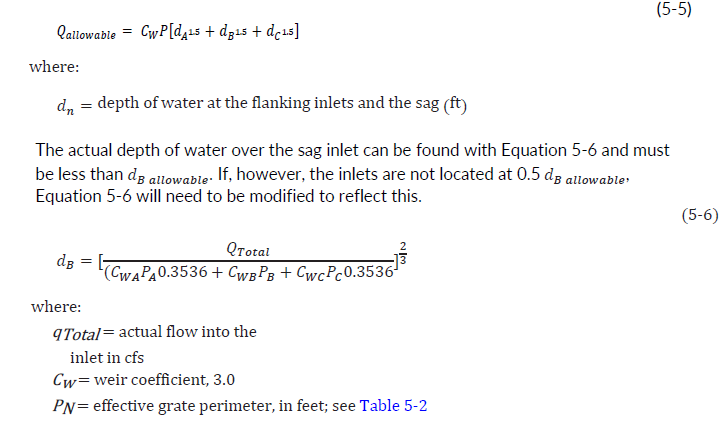
dB = actual depth of ponded water at the inlet in feet
After the analysis is completed, the PEO shall verify that the allowable depth and allowable flow have not been exceeded ![]() . If both the allowable depth and allowable flow are greater than the actual, then the maximum allowable spread will not be exceeded and the design is acceptable. If the actual depth or flow is greater than the allowable, then the runoff will spread beyond the maximum limits and the design is not acceptable. In this case, the PEO shall add flanking inlets or use different inlets that have larger openings. Additional flanking inlets should be placed close to the sag inlet to increase the flow interception and reduce the flow into the sag.
. If both the allowable depth and allowable flow are greater than the actual, then the maximum allowable spread will not be exceeded and the design is acceptable. If the actual depth or flow is greater than the allowable, then the runoff will spread beyond the maximum limits and the design is not acceptable. In this case, the PEO shall add flanking inlets or use different inlets that have larger openings. Additional flanking inlets should be placed close to the sag inlet to increase the flow interception and reduce the flow into the sag.