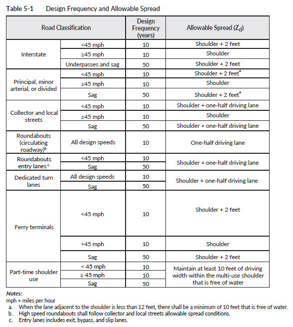
When stormwater is collected and carried along the roadside in a gutter, or next to a curb or barrier, the allowable top width of the flow prism (Zd) is dependent on the road classification, as noted in Table 5-1.
For design-bid-build projects, the PEO shall perform a gutter flow analysis for each construction staging plan of the project using the same allowable spread design criteria in Table 5-1. Not meeting the criteria in Table 5-1 is not considered a Hydraulics Manual deviation. The purpose of the required analysis is to identify areas of ponding water for the contractor to be aware of during the construction portion of the project. The gutter spread analysis shall be placed in the Temporary Erosion and Sediment Control (TESC) Plan, Abbreviated TESC Plan, or region equivalent document and shall have concurrence from the RHE.
For design-build projects, the design-builder shall perform a gutter flow analysis for each construction staging plan of the project using the same allowable spread design criteria in Table 5-1. Not meeting the criteria in Table 5-1 is not considered a Hydraulics Manual deviation. The purpose of the required analysis is to identify areas of ponding water for the design-builder to be aware of during construction of the project and for the design-builder to manage the risk accordingly. The gutter spread analysis shall be placed in the TESC Plan, Abbreviated TESC Plan, or Region equivalent document and shall have concurrence from the RHE.
WSDOT uses gutter flow capacity and inlet spacing (on continuous grades and at sumps) equations from the FHWA’s HEC-22. WSDOT gutter flow calculations shall use a uniform gutter section per HEC-22. The project shall only use uniform gutter sections as opposed to depressed gutter sections per HEC-22. The following specific sections of HEC-22 are used for gutter flow capacity and inlet spacing:
• 4.3.4: Flow in Sag Vertical Curves
• 4-4: Drainage Inlet Design
• 4-4.4: Interception Capacity of Inlets on Grade
• 4-4.5: Interception Capacity of Inlets in Sag Locations
• 4-4.6.2: Inlet Spacing on Continuous Grades
• 4-4.6.3: Flanking Inlets