The slope is calculated by dividing the vertical drop in the river channel by the horizontal distance measured along the channel centerline or along the thalweg, whichever applies for uniform flow or natural (non-uniform flow) channels, of a specific channel reach. Where slope (S) is needed to support Manning’s equation calculations, it can be measured in the field for typical channel conditions. Calculated channel slope is often referred to as the “rise over run,” whereby the “rise” in a channel is represented by the vertical change in channel elevation, and the run in a channel is the change in horizontal length between representative elevation points.
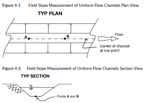
Both rise and run are measured along the lowest point of the channel. For channels that have assumed uniform geometries (i.e., same cross section and profile), which is typical of constructed gravity stormwater systems, roadside ditches and swales, roadway gutters, and can also include streams and conveyance channels, the lowest elevation point is typically along the middle of the bed of the channel, as shown in Figure 4-1 and Figure 4-2.
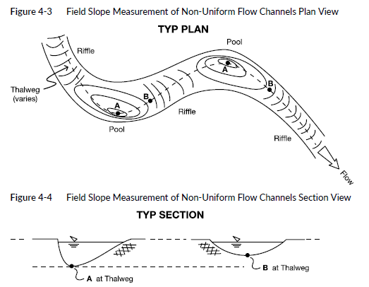
Where the channel has non-uniform geometries (i.e., changes gradient or channel dimensions), which is more typical of natural stream and river channels that have geomorphically governed characteristics (e.g., pools and riffles) but can also be constructed channels, the slope should be measured for each similar channel reach, and the results should be incorporated into the analysis so as to accurately represent the overall channel hydraulics. A reach is defined as a segment of the channel with similar hydraulic and geomorphic characteristics. In particular for natural channels, the gradient is typically measured along the thalweg, as shown in Figure 4-3 and Figure 4-4. The thalweg is the lowest channel elevation point for any given flow, typically located along the outside of bends, and then moves more to the center of the channel in straight reaches. The thalweg can change during peak flows.
In both uniform and non-uniform channels, the engineer may need to apply discretion in how the gradient reaches are assessed and/or combined to best represent the channel hydraulic conditions, and where the thalweg is located.
4-3.1.1 Uniform Flow Conditions:
Gravity Stormwater Systems, Roadside Ditches and Swales, Roadway Gutters, Streams, and Conveyance Channels
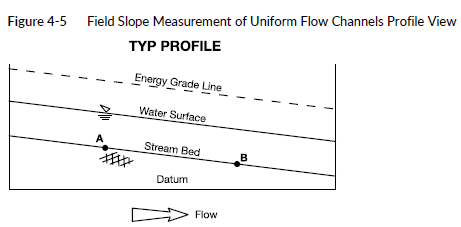
In constructed or natural channels with assumed uniform flow conditions (i.e., with corresponding uniform channel geometries and corresponding uniform flow depth, width, area, and velocity for the reach of interest) the channel bed gradient generally matches the top of flow gradient, as shown in Figure 4-5. Therefore, the vertical drop should be measured at points along the bed elevation represented by points A and B in Figure 4-5. If the channel does not allow for practical or safe access to measure the channel bed (e.g., flows are too deep, or suspended sediment does not allow safe or practical visibility of bed conditions), then measure from the top of the water surface. The horizontal distance should be measured between the two points where the bed or top of water points were located.
4-3.1.2 Non-Uniform Flow Conditions: Streams and Rivers
In natural channels with assumed non-uniform flow conditions (i.e., changes in channel depth, width, area, and/or velocity corresponding to variations in channel geometries at geomorphically governed pools or riffles along the channel reach of interest), the channel bed gradient may be different from the water surface gradient at various points along the channel, as shown in Figure 4-6. For example, the bed elevation may drop in pools along the channel, resulting in slower velocity and deeper flows, and then rise in riffles along the channel, resulting in shallower and faster velocity flows.
Figure 4-6 Field Slope Measurement of Non-Uniform Flow Channels Profile View
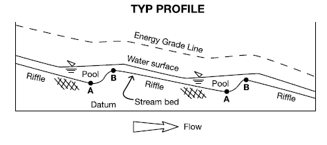
In these situations, it is important to measure bed elevations at similar geomorphic locations; otherwise, the resulting channel gradient may represent only localized flow conditions and could be artificially high or low when considering the reach flow conditions. For example, measuring the channel gradient at a pool and the next downstream riffle (see Figure 4-6, points A and B) could result in a localized flatter gradient, and similarly measuring from a riffle to the following downstream pool could result in a locally steeper gradient; neither of these situations accurately represents the reach flow conditions. Measurements should ideally be taken from “riffle-to-riffle,”
shown in Figure 4-6 as point B at the upstream end of the riffle to point B at the following downstream riffle.
4-3.1.3 Energy Grade Line
Note that in both uniform and non-uniform channel flow conditions, the most accurate representation of gradient for input into calculations is represented by the energy grade line (EGL). The EGL is generally represented as the sum of the flow depth and the velocity head. The concept of the EGL is presented here to recognize the basis for the standard of practice, and be able to reference back to more complex analyses, where needed; in practical terms the channel bed and/or water level is commonly used as a means for characterizing slope in calculations.
In uniform flow conditions the flow depth is generally constant and the resulting water surface is generally parallel to the bed elevation; therefore, the EGL is also typically parallel to the water surface, as shown in Figure 4-5 above. Simplified calculations using measured rise over run to estimate slope of the channel are therefore applicable.
In non-uniform flow conditions, where the depth of flow and gradient can vary corresponding to changes in channel geometry along the channel, the corresponding channel slope is better represented by the EGL, as shown in Figure 4-6. Non-uniform flow conditions are more difficult to accurately characterize with manual channel bed measurements and calculations. If no other options are available, then incorporate the methods described above for measuring channel slope, and the results should be qualified accordingly.
Because non-uniform flow conditions are more complex, and the measurement of channel geometries (i.e., elevations, sections, gradients, etc.) often requires special equipment and expertise to complete bathymetric surveys to capture that information, the methods of calculating corresponding hydraulic results incorporate the EGL and require using complex analyses and/or hydraulic modeling software tools. Contact the PEO for more information regarding more complex analyses.