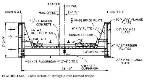
For long or heavily loaded bridge spans, restrictions on depth of structural system imposed by vertical clearances under a bridge generally favor use of through construction. Through girders support the deck near their bottom flange. Such spans preferably should contain only two main girders, with the railway or roadway between them (Fig. 12.46). In contrast, deck girders support the deck on the top flange (Art. 12.8).
The projection of the girders above the deck in through bridges may be objectionable for highway structures, because they obstruct the view from the bridge of pedestrians or drivers.
But they may offer the advantage of eliminating the need for railings and parapets. For railroad bridges over highways, streets, or other facilities from which the bridges are highly visible to the general public, through girders provide a more attractive structure than through trusses.
The projection of the girders above the deck also has the disadvantage of requiring special provisions for bracing the compression flange of the girders. Deck girders usually require no special provision for this purpose, because when a rigid deck is used, it provides the needed lateral support. Through girders should be laterally braced with gusset plates or knee braces with solid webs connected to the stiffeners.
In railroad bridges, spacing of the through girders should be at least 1â„20 of the span, or should be adequate to ensure that the girders and other structural components provide required clearances for trains, whichever is greater.
Article 12.11 presents an example to indicate the design procedure for a through girder bridge with floorbeams. Because the example in Art. 12.9 dealt with highway loading, additional information is provided by designing a railroad bridge in the following example.
Also, a curved alignment is selected, whereas the girders are kept straight, to illustrate the application of centrifugal forces to the structure. Note that because the girders are straight, the centerline of the track is offset from the centerline of the bridge. Design procedures not discussed in the example generally are the same as for deck girders (Art. 12.9) or plategirder stringers (Art. 12.4).
