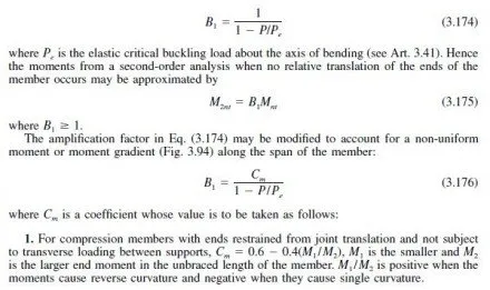
In the design of beams, girders, and trusses, the span should be taken as the distance between the center of gravity of supports. At supports, a flexural member should be restrained against torsion or rotation about its longitudinal axis. Usually, this requires that the top and bottom flanges of the beam be laterally braced. A slender flexural member seated atop a column may become unstable because of the flexibility of the columns if only the top flange is laterally restrained. Therefore, the bottom flange also must be restrained, by bracing or continuity at column connections, to prevent relative rotation between the beam and the column.
Flange Area
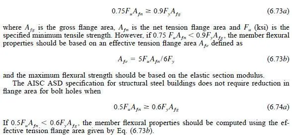
Rolled or welded shapes, plate girders and covered-plate beams should, in general, be proportioned by the flexural strength of the gross section. The AISC LRFD specification states
that no reduction should be made for bolt or rivet holes in either flange provided that
Welds and bolts connecting the flange to the web or joining a cover plate to a flange should be of adequate size to resist the total horizontal shear due to bending of the member.
In addition, flange-to-web connections should be adequate to transmit to the web any direct tension loads applied to the flange.
Cover plates used to increase the flexural strength of a beam should extend beyond the theoretical cutoff a distance sufficient to develop the capacity of the plate. The AISC LRFD specification gives specific requirements for the extension of a cover plate, which vary from one to two times the cover plate width.
Web Area
Webs are the shear-carrying elements of beams and girders. At any point along the length of a flexural member, the applied shear must be less than the strength of the gross web area, the product of the overall depth d and thickness tw of the web.
Generally, shear is not a controlling limit state for the design of a rolled shape. Webs of rolled shapes are thick enough that shear buckling does not occur. However, the shear strength of the web is a major design issue when proportioning a plate girder.
To prevent buckling of the compression flange of a plate girder into the web before the flange yields, both the ASD and LRFD specifications limit the web depth/ thickness ratio to
![]()
where h is the distance between adjacent lines of fasteners or clear distance between flanges for welded flange-to-web connections. However, when transverse stiffeners are utilized and they are spaced not more than 1.5h apart, the maximum depth/ thickness ratio is
![]()
In these equations, Fy is the yield stress of the flange steel, ksi.
Stiffener Requirements
Stiffeners are often a less costly alternative to increasing the thickness of the web to prevent buckling. Angles or plates normal to a web may be used as bearing stiffeners or transverse or longitudinal stiffeners to prevent buckling of the web.
Bearing stiffeners, when required at locations of concentrated loads or end reactions, should be placed in pairs, normal to and on opposite sides of the web. They should be designed as columns. The column section is assumed to consist of two stiffeners and a strip of the web. The web strip is taken as 25tw for interior stiffeners and 12tw for stiffeners at the end of the web. For computing the design strength of the assumed column section, the effective length may be taken as three-fourths of the stiffener length.
When the load normal to the flange is tensile, the stiffeners should be welded to the loaded flange. When the load normal to the flange is compressive, the stiffeners should either bear on or be welded to the loaded flange. It is essential that a load path exist for the stiffeners to contribute effectively to the member strength.
Transverse intermediate stiffeners, which may be attached to the web either singly or in pairs, increase the shear buckling strength of the web. The stiffeners also increase the carrying capacity of the web through tension-field action.

When bearing is not needed for transmission of a load or reaction, intermediate stiffeners may be stopped short of the tension flange a distance up to six times the web thickness. The stiffener-to-web weld should be stopped between four and six times the web thickness from the near toe of the web-to-flange weld.
A rectangular-plate compression flange, however, may twist unless prevented by stiffeners.
Hence single stiffeners should be attached to the compression flange. When lateral bracing is connected to stiffeners, the stiffeners should be attached to the compression flange with fasteners or welds capable of transmitting 1% of the total flange stress, unless the flange is composed only of angles.
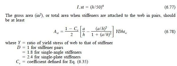
For design of a transverse stiffener, the AISC ASD and LRFD specifications establish minimum requirements for stiffener dimensions. For LRFD, the moment of inertia for a transverse stiffener used to develop the web design shear strength should be at least

The moment of inertia should be taken about an axis in the center of the web for stiffener pairs or about the face in contact with the web plate for single stiffeners. The LRFD specification also has requirements for the minimum area of stiffeners in slender web girders.
For ASD, the moment of inertia of a single stiffener or pair of stiffeners, with reference to an axis in the plane of the web, should be at least
For connecting stiffeners to girder webs, maximum spacing for bolts is 12 in center-tocenter.
Clear distance between intermittent fillet welds should not exceed 16 times the web thickness nor 10 in.
