The following shapes for truss members are typically considered:
H sections, made with two side segments (composed of angles or plates) with solid web, perforated web, or web of stay plates and lacing. Modern bridges almost exclusively use H sections made of three plates welded together.
Channel sections, made with two angle segments, with solid , perforated web, or web of stay plates and lacing. These are seldom used on modern bridges.
Single box sections, made with side channels, beams, angles and plates, or side segments of plates only. The side elements may be connected top and bottom with solid plates, perforated plates, or stay plates and lacing. Alternatively, they may be connected at the top with solid cover plates and at the bottom with perforated plates, or stay plates and
lacing. Modern bridges use primarily four-plate welded box members. The cover plates are usually solid, except for access holes for bolting joints.
Double box sections, made with side channels, beams, angles and plates, or side segments of plates only. The side elements may be connected together with top and bottom perforated cover plates, or stay plates and lacing.
To obtain economy in member design, it is important to vary the area of steel in accordance with variations in total loads on the members. The variation in cross section plus the use of appropriate-strength grades of steel permit designers to use essentially the weight of steel actually required for the load on each panel, thus assuring an economical design.
With respect to shop fabrication of welded members, the H shape usually is the most economical section. It requires four fillet welds and no expensive edge preparation. Requirements for elimination of vortex shedding, however, may offset some of the inherent economy of this shape.
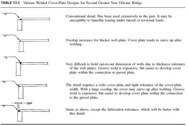
Box shapes generally offer greater resistance to vibration due to wind, to buckling in compression, and to torsion, but require greater care in selection of welding details. For example, various types of welded cover-plate details for boxes considered in design of the second Greater New Orleans Bridge and reviewed with several fabricators resulted in the observations in Table 13.5.
Additional welds placed inside a box member for development of the cover plate within the connection to the gusset plate are classified as AASHTO category E at the termination of the inside welds and should be not be used. For development of the cover plate within the gusset-plate connection, groove welds, large fillet welds, large gusset plates, or a combination of the last two should be used.
Tension Members. Where practical, these should be arranged so that there will be no bending in the members from eccentricity of the connections. If this is possible, then the total stress can be considered uniform across the entire net area of the member. At a joint, the greatest practical proportion of the member surface area should be connected to the gusset or other splice material.
Designers have a choice of a large variety of sections suitable for tension members, although box and H-shaped members are typically used. The choice will be influenced by the proposed type of fabrication and range of areas required for tension members. The design should be adjusted to take full advantage of the selected type. For example, welded plates are economical for tubular or box-shaped members. Structural tubing is available with almost 22 in2 of cross-sectional area and might be advantageous in welded trusses of moderate spans. For longer spans, box-shape members can be shop-fabricated with almost unlimited areas.
Tension members for bolted trusses involve additional considerations. For example, only 50% of the unconnected leg of an angle or tee is commonly considered effective, because of the eccentricity of the connection to the gusset plate at each end.
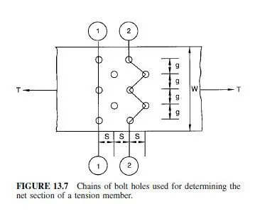
To minimize the loss of section for fastener holes and to connect into as large a proportion of the member surface area as practical, it is desirable to use a staggered fastener pattern.
In Fig. 13.7, which shows a plate with staggered holes, the net width along Chain 1-1 equals plate width W, minus three hole diameters. The net width along Chain 2-2 equals W, minus five hole diameters, plus the quantity S2/4g for each off four gages, where S is the pitch and g the gage.
Compression Members. These should be arranged to avoid bending in the member from eccentricity of connections. Though the members may contain fastener holes, the gross area may be used in design of such columns, on the assumption that the body of the fastener fills the hole. Welded box and H-shaped members are typically used for compression members in trusses.
Compression members should be so designed that the main elements of the section are connected directly to gusset plates, pins, or other members. It is desirable that member components be connected by solid webs. Care should be taken to ensure that the criteria for slenderness ratios, plate buckling, and fastener spacing are satisfied.
Posts and Hangers. These are the vertical members in truss bridges. A post in a Warren deck truss delivers the load from the floorbeam to the lower chord. A hanger in a Warren through-truss delivers the floorbeam load to the upper chord. Posts are designed as compression members. The posts in a single-truss span are generally made identical. At joints, overall dimensions of posts have to be compatible with those of the top and bottom chords to make a proper connection at the joint.
Hangers are designed as tension members. Although wire ropes or steel rods could be used, they would be objectionable for esthetic reasons. Furthermore, to provide a slenderness ratio small enough to maintain wind vibration within acceptable limits will generally require rope or rod area larger than that needed for strength.
Truss-Member Connections. Main truss members should be connected with gusset plates and other splice material, although pinned joints may be used where the size of a bolted joint would be prohibitive. To avoid eccentricity, fasteners connecting each member should be symmetrical about the axis of the member. It is desirable that fasteners develop the full capacity of each element of the member. Thickness of a gusset plate should be adequate for resisting shear, direct stress, and flexure at critical sections where these stresses are maximum.
Re-entrant cuts should be avoided; however, curves made for appearance are permissible.
