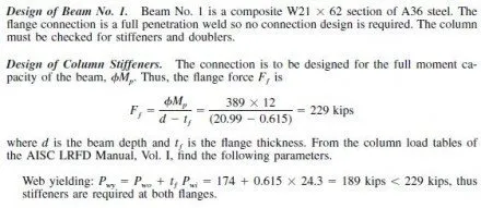
The most commonly used moment connection is the field welded connection shown in Fig. 5.56. This connection has been in common use throughout the U.S. for many years. In current seismic design covered by the AISC Seismic Provisions for Structural Steel Buildings, it is permitted for use in ordinary moment-resisting frames (Art. 9.7) without requirements for physical testing. It is also permitted for use in special moment-resisting frames, when the member sizes used for the specific project have been tested to demonstrate that the required ductility level can be achieved. Furthermore, it is widely used in areas of low seismicity where the AISC seismic provisions do not apply, and in frames designed primarily for wind and gravity forces, such as in the following example.
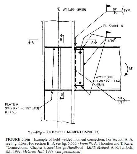
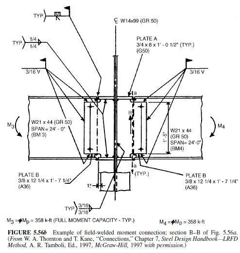
Example Three Way Moment Connection AISC LRFD. The moment connection of Fig. 5.56a is a three-way moment connection. Additional views are shown in Figs. 5.56b and 5.56c. If the strong axis connection requires stiffeners, there will be an interaction between the flange forces of the strong and weak axis beams. If the primary function of these moment connections is to resist lateral maximum load from wind or seismic sources, the interaction can generally be ignored because the maximum lateral loads will act in only one direction at any one time. If the moment connections are primarily used to carry gravity loads, such as would be the case when stiff floors with small deflections and high natural frequencies are desired, there will be interaction between the weak and strong beam flange forces. The calculations here will be for a wind or a seismic condition in a region of low to moderate seismicity, but interaction will be included to demonstrate the method.
Following common practice based on tests, the load path assumed here is that the moment is carried entirely by the flanges, and the shear entirely by the web. Proceeding to the connection design, the strong axis beam, beam No. 1, will be designed first.
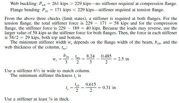
The minimum stiffener length ls depends on the column depth, dc, and the flange thickness
of the column, tÆ’c:

The minimum length is for a half depth stiffener, which is not possible in this example
because of the weak axis connections. Therefore, use a full depth stiffener, 121â„2 in long.
A final stiffener size consideration is a plate buckling check which requires that


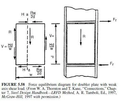
column), then the free body diagram of Fig. 5.58 is possible. In this figure, all of the shear force R is delivered to the side of the doubler where it is opposite in direction to the shear delivered by the moment connection, thereby avoiding over-stressing the other side where the two shears would add. Since the doubler and its welds are capable of carrying V or R alone, they are capable of carrying their difference. The same argument applies to the top and bottom edges of the doubler. Also, the same argument holds if the moment and/or weak axis shear reverse(s).
